
Copyright 2011. figNoggle Designs.
7x10, 7x12, 7x14 Mini-Lathe Information
Website Links
Post a link to your website or view other hobby and machine and metalworking websites for free.
|
Rent Mill & Lathe DVDs at Smartflix | Great aluminum & steel prices at OnlineMetals Bridgeport Boss head teardown
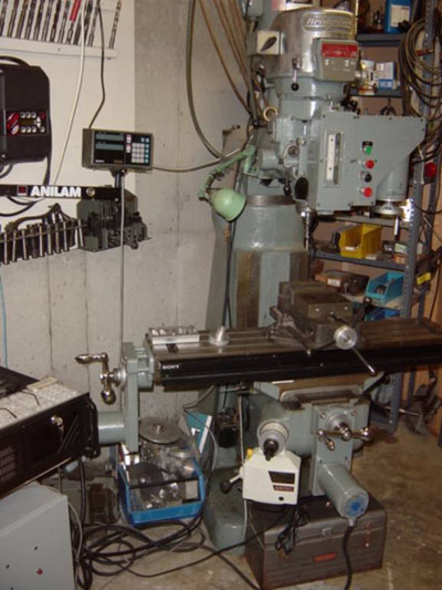
By Peter Reilley micrio (the at sign) mv (a dot) com I picked up an old Bridgeport Boss head. I believe that it is a Boss 3 because the stepper motor cooling fins are horizontal rather than vertical as all the newer versions had. This is the first generation of Bridgeport CNC machines. I believe that the basic Boss Z axis drive remained the same up through the Boss 10. I believe that this drive is the same as is used in the rigid ram mills even though the housing is different. The Boss Z axis drives have a reputation of being bullet proof. The Boss head Z drive was a mystery to be before I took this one apart. If it is a mystery to anyone else then this article may help. I intend to replace the head on my
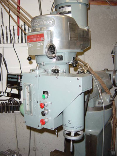
This is the Wesel Z axis drive.
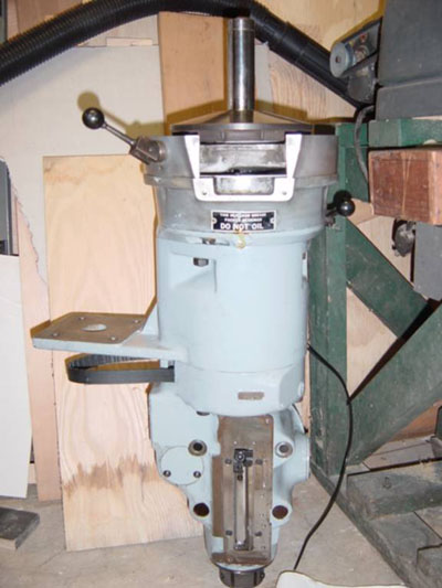
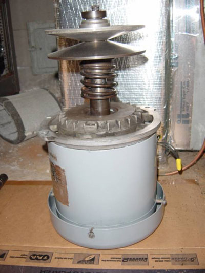
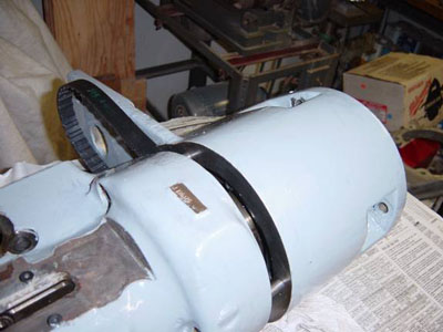
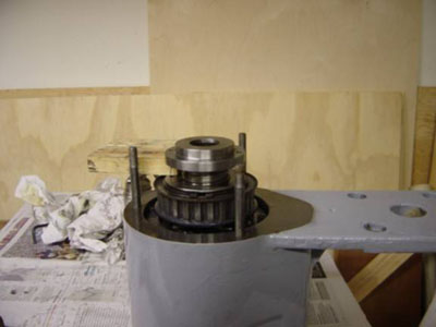
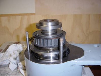
This is the Boss head that I am going to use. I have removed the motors and most of the vari-drive to make it easier to handle. The spindle drive section of Boss mills is very similar to the vari-drive manual mills. The principle difference is that the motor is mounted with its drive shaft upward in the Boss mill. The manual mill had the motor shaft facing downward. Thus, the aluminum housings that contain the vari-drive are different even though they look similar. The forward vari-drive assembly is the same between the Boss and the manual mills. I believe that the motor and the vari-drive shives are the same between the manual mill and the Boss mill. They are different is the way that the sheves are assembled. In the manual mill the spring is outermost on the shaft and the fixed sheve is next to the motor. The Boss has the spring next to the motor and the fixed sheve outermost. I have assembled both and either one could be assembled for the manual mill or the Boss mill. Astute observers will notice a bolt on the end of the shaft. This is a modification that holds the fixed sheve in place because the shaft and the snap ring grove get messed up from long use.
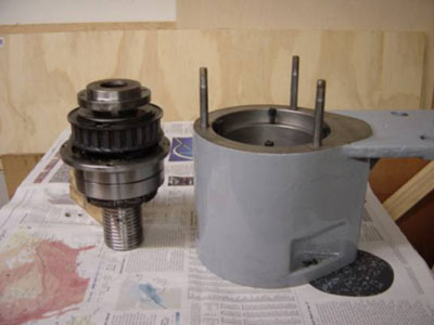
I am not going to talk much about the vari-drive since it as about the same as for the manual mills and is not much of a mystery. This picture shows separation of the Z axis drive section from the quill section. As you separate them be sure that the ball nut does not unscrew from the ball screw. If this happens then all of the small ball bearings will go flying. At this point you can remove the quill by pulling it out with the Z axis drive section.
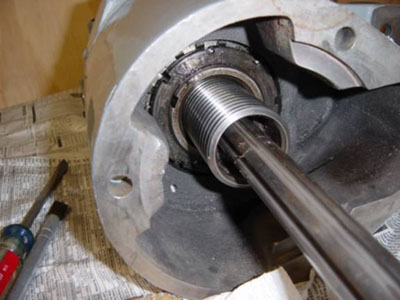
This is a view of the top of the ball screw. The ball nut is visible around the ball screw. As you can see there is nothing to stop the ball nut from coming off the end of the ball screw. If this happens then all the ball bearings will fall out.
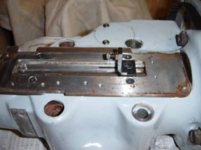
If you choose the pull the quill out with the Z axis drive then you must remove the quill guide device as shown below. This prevents the quill from rotating and serves to actuate the limit switches.
If you want to separate the quill from the ball screw, you must remove the 6 Allen screws that attach the ball screw to the top of the quill. Be very careful that you don't let the ball nut unscrew from the ball screw.
Once all the screws are out you can separate the two halves.
This is the bottom of the Z axis drive assembly. The cog pulley that is driven by the stepper motor is visible.
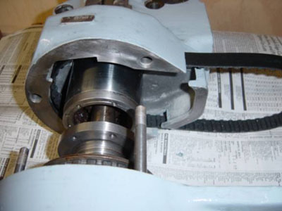
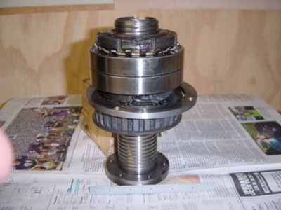
. At this point I am pressing the ball screw assembly out of the housing. The large ball bearings the mount the ball nut can be seen. The ring that holds the bearings into the housing can be seen below the pulley.
There is the ball screw assembly separated from the housing. Notice the piece of wood holding the ball nut up. Without the wool the ball but would unscrew from the ball screw due to gravity.
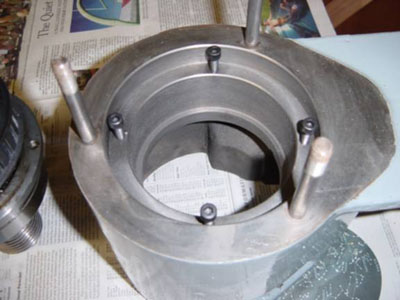
This is the inside of the housing. The 4 Allen bolts hold the ball nut into the housing.
I am beginning to slide the cog pulley off the ball nut. You can see the ball bearing channels under the pulley. Above the pulley are two large ball bearings that hold the ball nut in the housing. The ball nut is spun by the Z axis motor and the ball screw does not spin.
Here I have the cog belt pulley removed from the ball nut. You can see the ball bearing recirculating channels. These are hidden by the pulley. The pulley is held in place by the large snap ring.
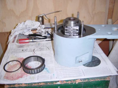
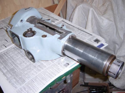
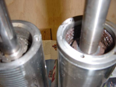
I am removing the quill from the lower housing. The lower housing used on the Boss is the same as is used on the manual mill except that unused features are not machines. Thus, the Z axis feed areas exist but are not machined. I believe that you could put a Boss Z axis drive on top of a manual mill lower housing.
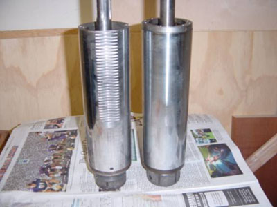
The quills between the Boss and the manual mull are not exactly the same. On the left is the quill from a manual mill and on the right is a Boss quill. The manual mill has a rack cut in the quill.
The manual mill does not have the holes for the ball screw drilled into the top of the quill.
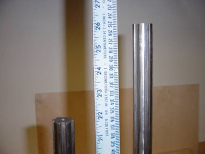
The spindle is longer in the Boss mill. The spindle on the left is a Kwik switch 200. You can see that it is not drilled for a draw bar. The Boss spindle on the right is a NMTB 30 that is drilled for a draw bar.
I hope that this helps people understand the Boss Z axis drive. If you have any questions please email me. Pete Jan. 21, 2007
Reprinted with permission. This content is hosted free of charge for the benefit of the machinists community. |

Looking for mini-mill help and how-tos? How about lathe help and how-tos?
We're prototyping a benchtop CNC vertical mill using the DigiSpeed-XL interface card for Mach, Dart Controls and KB Electronics KBIC/KBMM 90VDC motor controllers, 1.5HP treadmill motor from Surplus Center and a R8-spindle head from the X2 mini-mill - not to mention Gecko servo drives and an entirely closed-loop system. Come take a look!CNC 8x12 Lathe
Check out our newest developments like the CNC/DRO 8x12/8x14 lathe using Gecko drives, break-out board, NEMA 34 step motors, DRO and more!
SUPERX3.COM
Sieg X3 and Super X3 Grizzly G0463 Info
MDAHacks.com
T-Mobile MDA / Cingular 8125 / HTC Wizard Hacks, Tweaks, Tips, Tricks and More!
Metal Working FAQ.NET
Your source for metalworking and machining, tips, tricks, and more. Over 50 content wiki sites!