(278,’2007-03-14 08:26:08′,’david’,’2007-03-14 08:35:38′,’david’,’CNC 8×12 Mini-Lathe Z-Axis Day 2 – It Works!’,”,’On Day 1 of this build we showed the basic layout of the Z-axis ballscrew location and turning of the ballscrew using ground HSS bits over carbide inserts. Day 2 actually took two days itself but will be combined into one.
Most of the time was spent using sneaker-net to transfer G programs from the laptop to the host rackmounted cnc controller (that is until we hooked up a crossover cable between the two machines so that the programs could be sent via NetBEUI and eliminate moving the compact flash card back and forth). There was also considerable time involved setting up the workpiece in the mill since using the cnc mini-mill had its work envelope limitations appear on a piece as large as the bed-end motor bracket – sized at just around 4″ wide and 8″ long. As you can see, the workpiece had to be remounted many times over to get certain cuts made. This in turn required re-generating toolpaths many times over – a very time consuming process overall.
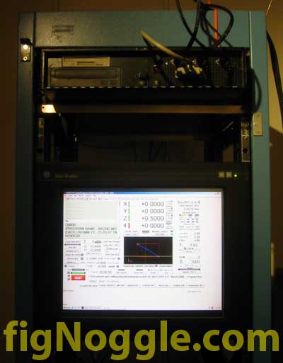
First let’s talk a bit about the control setup. We’re still using our CNC mini-mill (converted X2 mini-mill) with the 1U server rackmount case only this time it was mounted in an actual server rack with an accompanying 18.1″ capacitive touch screen monitor from Allen Bradley. The capacitive touch means that it requires the use of your bare finger, elbow or other ungloved extremety to activate the screen’s response. Unfortunately, since it’s not a passive touch screen, the use of a stylus could not be used.
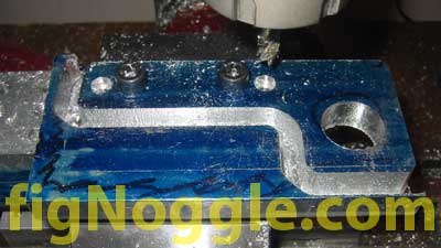
The previous picture you saw was a blue layout dye’d motor plate that had been partially cut and was prepped for bed hole marking.
We started with a piece of 1/2″ thick aluminum plate 4″ wide by roughly 12″ long. Since we knew that remounting and reindexing the part was crucial to this part being made, we brought back from life in one of the tool chests, the threaded block with equally spaced holes that we had created as a project a while back. Here’s a tip (we’ll show you this later): make or buy yourself a mounting plate with equally spaced threaded holes that accommodate step-block sized holes so that complex workpiece mounting can be accomplished. It’ll increase the speed in setups.
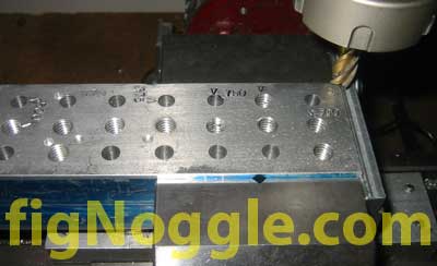
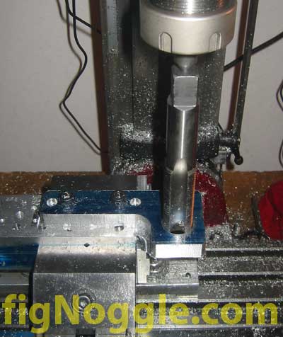
After laying out the general centerline of the workpiece with ENCO layout dye (use Dykem, it’s much better), we drilled the two 5/16″ holes so that it could be mounted to the block.
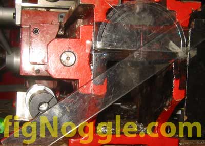
We missed a step! Here’s a picture of the protractor and ruler taped together at the end of the bed to give us a general layout guide for dimensioning of this motor plate to be machined:
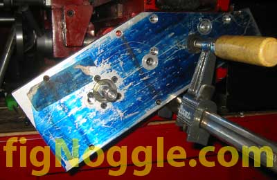
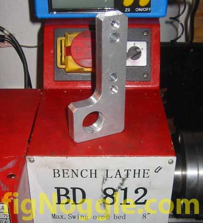
After many hours of redrawing toolpaths and playing around with the design and remounting the workpiece, making finite adjustments here and there, we ended up with the motor bracket:
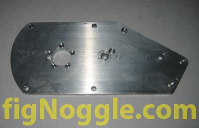
You’ll notice that there was an OOPS! made in the plate. We didn’t pay enough attention to the toolpath simulation which caused us to move the plate over in the X-axis a few times until the moutning holes interefered with the actual part holes. They were supposed to be equally spaced.. What happened was that given our lead-in/lead-out of the contour cut of the long angle, we didn’t retract the toolbit. We kept the tool down. This of course led to the cutter cutting the plate as it moved back for more depth cut passes. By the time we figured out we had made this mistake, it was too late. Either scrap the part and start over or use it as-is realizing that it wouldn’t look good in the end. It’s a prototype and we left it as-is.
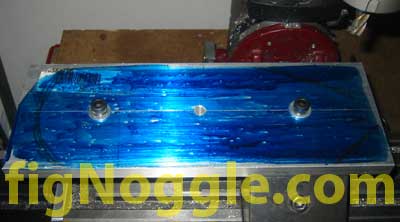
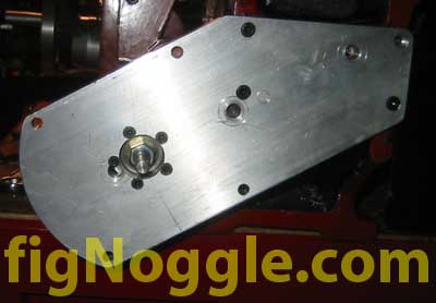
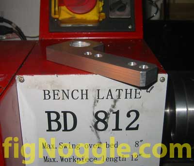
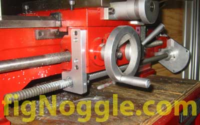
After making the final counter-bored holes for the bearing block, rounding off the end of the motor plate (to make it look nice), it was mounted to the end of the lathe bed:
Now it was time to layout the ball nut flange to mount to the carriage or apron. Originally, the plan was to mount it to the underside of the carriage (which we may still end up doing), but we opted to keep things simple by mounting it to the side of the apron. As a result, the ball nut flange required nothing more than a plate with some mouting holes.
We start by drilling mounting holes in the plate. Here, you’ll see the versatility of using plates/blocks with these series of threaded holes as we’re using step clamps to hold down the workpiece while the block is held down in a screwless vise.
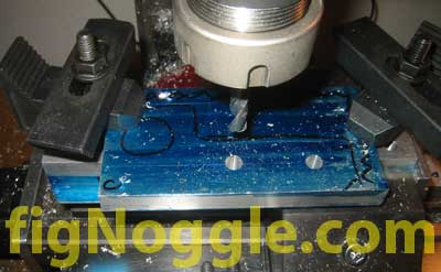
Again, we had to reposition the entire vise and re-zero (another tip here is to create a method of indexing the table so that the vise can be moved into position without having to always re-zero to allow for work envelope constraints. After we moved the vise back some, the ballnut flange was machined without having to reposition the workpiece. A few small counterbored holes, a hole for the 5/8″dia. ball nut thead, and a contour produced the flange.
 (Contouring)
 (Threading by hand)
 (Completed)
 (Look at the excellent finish!)
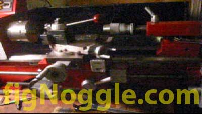
Finally, drilling and tapping corresponding holes on the side of the apron produced a fitted ballscrew/ball nut assembly that drives or can be driven resulting in a manual AND CNC lathe:
Here’s a video of the carriage being driven back and forth with a cordless drill chucked to the ballscrew shaft (click on the image to view the video):
We still need to mount the motor and then we’ll power it up and follow up in another post. ‘,’
On Day 1 of this build we showed the basic layout of the Z-axis ballscrew location and turning of the ballscrew using ground HSS bits over carbide inserts. Day 2 actually took two days itself but will be combined into one.
Most of the time was spent using sneaker-net to transfer G programs from the laptop to the host rackmounted cnc controller (that is until we hooked up a crossover cable between the two machines so that the programs could be sent via NetBEUI and eliminate moving the compact flash card back and forth). There was also considerable time involved setting up the workpiece in the mill since using the cnc mini-mill had its work envelope limitations appear on a piece as large as the bed-end motor bracket – sized at just around 4” wide and 8” long. As you can see, the workpiece had to be remounted many times over to get certain cuts made. This in turn required re-generating toolpaths many times over – a very time consuming process overall.
First let’s talk a bit about the control setup. We’re still using our CNC mini-mill (converted X2 mini-mill) with the 1U server rackmount case only this time it was mounted in an actual server rack with an accompanying 18.1” capacitive touch screen monitor from Allen Bradley. The capacitive touch means that it requires the use of your bare finger, elbow or other ungloved extremety to activate the screen’s response. Unfortunately, since it’s not a passive touch screen, the use of a stylus could not be used.
The previous picture you saw was a blue layout dye’d motor plate that had been partially cut and was prepped for bed hole marking.
We started with a piece of 1/2” thick aluminum plate 4” wide by roughly 12” long. Since we knew that remounting and reindexing the part was crucial to this part being made, we brought back from life in one of the tool chests, the threaded block with equally spaced holes that we had created as a project a while back. Here’s a tip (we’ll show you this later): make or buy yourself a mounting plate with equally spaced threaded holes that accommodate step-block sized holes so that complex workpiece mounting can be accomplished. It’ll increase the speed in setups.
After laying out the general centerline of the workpiece with ENCO layout dye (use Dykem, it’s much better), we drilled the two 5/16” holes so that it could be mounted to the block.
We missed a step! Here’s a picture of the protractor and ruler taped together at the end of the bed to give us a general layout guide for dimensioning of this motor plate to be machined:
After many hours of redrawing toolpaths and playing around with the design and remounting the workpiece, making finite adjustments here and there, we ended up with the motor bracket:
You’ll notice that there was an OOPS! made in the plate. We didn’t pay enough attention to the toolpath simulation which caused us to move the plate over in the X-axis a few times until the moutning holes interefered with the actual part holes. They were supposed to be equally spaced.. What happened was that given our lead-in/lead-out of the contour cut of the long angle, we didn’t retract the toolbit. We kept the tool down. This of course led to the cutter cutting the plate as it moved back for more depth cut passes. By the time we figured out we had made this mistake, it was too late. Either scrap the part and start over or use it as-is realizing that it wouldn’t look good in the end. It’s a prototype and we left it as-is.
After making the final counter-bored holes for the bearing block, rounding off the end of the motor plate (to make it look nice), it was mounted to the end of the lathe bed:
Now it was time to layout the ball nut flange to mount to the carriage or apron. Originally, the plan was to mount it to the underside of the carriage (which we may still end up doing), but we opted to keep things simple by mounting it to the side of the apron. As a result, the ball nut flange required nothing more than a plate with some mouting holes.
We start by drilling mounting holes in the plate. Here, you’ll see the versatility of using plates/blocks with these series of threaded holes as we’re using step clamps to hold down the workpiece while the block is held down in a screwless vise.
Again, we had to reposition the entire vise and re-zero (another tip here is to create a method of indexing the table so that the vise can be moved into position without having to always re-zero to allow for work envelope constraints. After we moved the vise back some, the ballnut flange was machined without having to reposition the workpiece. A few small counterbored holes, a hole for the 5/8“dia. ball nut thead, and a contour produced the flange.
(Contouring)
(Threading by hand)
(Completed)
(Look at the excellent finish!)
Finally, drilling and tapping corresponding holes on the side of the apron produced a fitted ballscrew/ball nut assembly that drives or can be driven resulting in a manual AND CNC lathe:
Here’s a video of the carriage being driven back and forth with a cordless drill chucked to the ballscrew shaft (click on the image to view the video):
We still need to mount the motor and then we’ll power it up and follow up in another post.
‘,’On Day 1 of this build we showed the basic layout of the Z-axis ballscrew location and turning of the ballscrew using ground HSS bits over carbide inserts. Day 2 actually took two days itself but will be combined into one.
Most of the time was spent using sneaker-net to transfer G programs from the laptop to the host rackmounted cnc controller (that is until we hooked up a crossover cable between the two machines so that the programs could be sent via NetBEUI and eliminate moving the compact flash card back and forth). There was also considerable time involved setting up the workpiece in the mill since using the cnc mini-mill had its work envelope limitations appear on a piece as large as the bed-end motor bracket – sized at just around 4″ wide and 8″ long. As you can see, the workpiece had to be remounted many times over to get certain cuts made. This in turn required re-generating toolpaths many times over – a very time consuming process overall.
‘,’
On Day 1 of this build we showed the basic layout of the Z-axis ballscrew location and turning of the ballscrew using ground HSS bits over carbide inserts. Day 2 actually took two days itself but will be combined into one.
Most of the time was spent using sneaker-net to transfer G programs from the laptop to the host rackmounted cnc controller (that is until we hooked up a crossover cable between the two machines so that the programs could be sent via NetBEUI and eliminate moving the compact flash card back and forth). There was also considerable time involved setting up the workpiece in the mill since using the cnc mini-mill had its work envelope limitations appear on a piece as large as the bed-end motor bracket – sized at just around 4” wide and 8” long. As you can see, the workpiece had to be remounted many times over to get certain cuts made. This in turn required re-generating toolpaths many times over – a very time consuming process overall.
‘,”,’8x128x14-Small-Lathe’,”,1,’Comment’,0,4,1,1,’article’,”,”,’cnc-8×12-mini-lathe-z-axis-day-2-it-works’,”,”,”,”,”,”,”,”,”,”,’c122295a3ed32e7445de34df8fcc61ff’,’2007-03-14′);