8×12/14 Lathe Compared To The 7×12 and 9×20 Lathes And The Resulting Modification Checklist

(270,’2007-02-06 17:27:21′,’david’,’2007-02-07 09:50:25′,’david’,’8×12/14 Lathe Compared To The 7×12 and 9×20 Lathes And The Resulting Modification Checklist’,”,’This list is not an exhaustive one nor does it imply that we’ll be working on these modifications to this lathe. Funny, some might wonder why even perform these in the first place given that the next step “up” is the 9″x20″ (sometimes dimensioned as the 9″x19″) lathe from Harbor Freight 45861 BV920 (older 40444), Grizzly G4000, Jet BD-920N or other variants and has only some of the features and benefits of the 8x.

Price has a lot to do with this. At just $100 over the price of the 7×10/12 mini-lathes during non-sale times (on sale, the 8x can be had for $439!), it’s way heftier of a machine. Remember that in machinery, mass counts! The 8×12/14 even weighs in over the 9×20. Imagine that!

Having said that, the features provided on the 8x have certainly a lot to be desired. As compared to the 7x, the 8x lacks the variable speed motor which is really convenient for threading using the “quasi backgear” of the motor at low speeds (this prevents munching the threads or worse, having your carriage jam into the headstock – don’t ask us how we know this :) ) and a reverse feed for left-hand threading or feeding away from the headstock (perhaps not as useful a feature to some, but still nice to have). The 7x and 8x really can’t compare in mass. The 8x wins hands-down, so this is kind of like comparing apples to oranges.

A better “opponent” (if you will) for the purposes of this article is the 9×20 lathe. A very popular and widespread machine (like the 7x) also has its advantages over the 8x. First, let’s talk price. At $800 non-sale pricing, the 9x costs about 45% more than the 8x also at non-sale pricing. Now, provided you can wait, when the 9×20 goes on sale at Harbor Freight and the stars align, you’ll be lucky enough to also apply the infamous 20% coupon (really, it’s just about 12%-15% due to state sales tax – unless of course, you’re lucky here as well) and take home the 9×20 at around the price of the 8x at non-sale prices. What do you get? The 9x has two major advantages over the 8x. Firstly, the quick change gear box (QCGB). Secondly, a longer bed. Both lathes need belt changes to change speeds. This is certainly not as convenient as the 7x feature, but this can easily be improved upon. Both lathes lack a tumbler reverse for doing left-hand threading like the 7x. This modification is also not to difficult to add (we haven’t had the need yet..). The 9x has the distinct advantage over the 8x and 7x in that a simple movement of a lever dictates the feed rate of the feedscrew. More on this issue later..\r\n \r\nThe other interesting thing to note is that the 9x has a threaded spindle whereas the 8x does not. This may matter should reverse work be performed. You certainly wouldn’t want the chuck to work its way off the spindle (but there’s a set screw to hold it in place..). Unfortunately none have the convenience of the D1-4 camlock system. You’d have to upgrade to a 12″x36″ or even 13″x40″ lathe to get this and other wonderful features – but at a price!

Back to the 8x versus 9x and the modifications. Adding some variable speed motor or variable frequency drive and eliminating belts for spindle speed changes would benefit both lathes, so it’s worth mentioning, but it’s not indicative of a shortcoming in this comparison exercise. Adding a tumbler reverse. Same. Now, here’s where things get interesting… Grizzly sells replacement parts for the G4000 lathe. If you were to buy the entire assembly for the gear change box and its internals, that totals $160 or so. This may be a worthwhile modification to the 8x since changing gears for feeds is a major slowdown in the pace of machining. We are actively investigating this option (along with the E-leadscrew or electronic leadscrew project that promises something in between CNC and the problem faced with change gears for feeding).

Onto the list. We think that the modifications to make this lathe an even better machine with nearly all the beneficial features of the others mentioned would be:

1. variable speed motor to eliminate belt changes for spindle speed\r\n2. quick change gear box to eliminate gear changes for feeding\r\n3. tumbler reverse to allow for left-hand threading

On the other hand, if you like KISS (keep it simple, stupid), the 8×12/14 does just that. No electronics to fry, no gearbox to crunch (not that this ever happens). It’s a basic, heavy-duty but small lathe for home workshop. And, did we mention that it’s a really great, nicely built machine? We really enjoy this lathe over the 7x despite its feature shortcomings. We don’t have enough playtime with the 9×20 to make useful comments. If the stars align for us, then the 9×20 will be an interesting addition to the shop, but in reality, we’re keeping our eyes open for a 12×36 or 13×40 lathe. Even the recent addition to the Grizzly line-up makes for an interesting double-take. The 10×22, with its 1″ spindle bore, and gearbox, not to mention the additional 100lb. mass increase over the 9x for “only” $170 more, makes this an even more compelling contender for the 9×20.

We’ll be adding this entry should the list change.’,’

This list is not an exhaustive one nor does it imply that we’ll be working on these modifications to this lathe. Funny, some might wonder why even perform these in the first place given that the next step “up” is the 9“x20” (sometimes dimensioned as the 9“x19”) lathe from Harbor Freight 45861 BV920 (older 40444), Grizzly G4000, Jet BD-920N or other variants and has only some of the features and benefits of the 8x.

Price has a lot to do with this. At just $100 over the price of the 7×10/12 mini-lathes during non-sale times (on sale, the 8x can be had for $439!), it’s way heftier of a machine. Remember that in machinery, mass counts! The 8×12/14 even weighs in over the 9×20. Imagine that!

Having said that, the features provided on the 8x have certainly a lot to be desired. As compared to the 7x, the 8x lacks the variable speed motor which is really convenient for threading using the “quasi backgear” of the motor at low speeds (this prevents munching the threads or worse, having your carriage jam into the headstock – don’t ask us how we know this :) ) and a reverse feed for left-hand threading or feeding away from the headstock (perhaps not as useful a feature to some, but still nice to have). The 7x and 8x really can’t compare in mass. The 8x wins hands-down, so this is kind of like comparing apples to oranges.

A better “opponent” (if you will) for the purposes of this article is the 9×20 lathe. A very popular and widespread machine (like the 7x) also has its advantages over the 8x. First, let’s talk price. At $800 non-sale pricing, the 9x costs about 45% more than the 8x also at non-sale pricing. Now, provided you can wait, when the 9×20 goes on sale at Harbor Freight and the stars align, you’ll be lucky enough to also apply the infamous 20% coupon (really, it’s just about 12%-15% due to state sales tax – unless of course, you’re lucky here as well) and take home the 9×20 at around the price of the 8x at non-sale prices. What do you get? The 9x has two major advantages over the 8x. Firstly, the quick change gear box (QCGB). Secondly, a longer bed. Both lathes need belt changes to change speeds. This is certainly not as convenient as the 7x feature, but this can easily be improved upon. Both lathes lack a tumbler reverse for doing left-hand threading like the 7x. This modification is also not to difficult to add (we haven’t had the need yet..). The 9x has the distinct advantage over the 8x and 7x in that a simple movement of a lever dictates the feed rate of the feedscrew. More on this issue later..

The other interesting thing to note is that the 9x has a threaded spindle whereas the 8x does not. This may matter should reverse work be performed. You certainly wouldn’t want the chuck to work its way off the spindle (but there’s a set screw to hold it in place..). Unfortunately none have the convenience of the D1-4 camlock system. You’d have to upgrade to a 12“x36” or even 13“x40” lathe to get this and other wonderful features – but at a price!

Back to the 8x versus 9x and the modifications. Adding some variable speed motor or variable frequency drive and eliminating belts for spindle speed changes would benefit both lathes, so it’s worth mentioning, but it’s not indicative of a shortcoming in this comparison exercise. Adding a tumbler reverse. Same. Now, here’s where things get interesting… Grizzly sells replacement parts for the G4000 lathe. If you were to buy the entire assembly for the gear change box and its internals, that totals $160 or so. This may be a worthwhile modification to the 8x since changing gears for feeds is a major slowdown in the pace of machining. We are actively investigating this option (along with the E-leadscrew or electronic leadscrew project that promises something in between CNC and the problem faced with change gears for feeding).

Onto the list. We think that the modifications to make this lathe an even better machine with nearly all the beneficial features of the others mentioned would be:

1. variable speed motor to eliminate belt changes for spindle speed
\n2. quick change gear box to eliminate gear changes for feeding
\n3. tumbler reverse to allow for left-hand threading

On the other hand, if you like KISS (keep it simple, stupid), the 8×12/14 does just that. No electronics to fry, no gearbox to crunch (not that this ever happens). It’s a basic, heavy-duty but small lathe for home workshop. And, did we mention that it’s a really great, nicely built machine? We really enjoy this lathe over the 7x despite its feature shortcomings. We don’t have enough playtime with the 9×20 to make useful comments. If the stars align for us, then the 9×20 will be an interesting addition to the shop, but in reality, we’re keeping our eyes open for a 12×36 or 13×40 lathe. Even the recent addition to the Grizzly line-up makes for an interesting double-take. The 10×22, with its 1” spindle bore, and gearbox, not to mention the additional 100lb. mass increase over the 9x for “only” $170 more, makes this an even more compelling contender for the 9×20.

We’ll be adding this entry should the list change.

‘,’This list is not an exhaustive one nor does it imply that we’ll be working on these modifications to this lathe. Funny, some might wonder why even perform these in the first place given that the next step “up” is the 9″x20″ (sometimes dimensioned as the 9″x19″) lathe from Harbor Freight 45861, Gtizzly G4000, Jet BD-920N or other variants and has some of the features and benefits of the 8x.

Price has a lot to do with this. At just $100 over the price of the 7×10/12 mini-lathes during non-sale times (on sale, the 8x can be had for $439!), it’s way heftier of a machine. Remember that in machinery, mass counts! The 8x even weighs in over the 9x. Imagine that! But wait, there’s more…’,’

This list is not an exhaustive one nor does it imply that we’ll be working on these modifications to this lathe. Funny, some might wonder why even perform these in the first place given that the next step “up” is the 9“x20” (sometimes dimensioned as the 9“x19”) lathe from Harbor Freight 45861, Gtizzly G4000, Jet BD-920N or other variants and has some of the features and benefits of the 8x.

Price has a lot to do with this. At just $100 over the price of the 7×10/12 mini-lathes during non-sale times (on sale, the 8x can be had for $439!), it’s way heftier of a machine. Remember that in machinery, mass counts! The 8x even weighs in over the 9x. Imagine that! But wait, there’s more…

‘,”,’8x128x14-Small-Lathe’,’Sieg-7x107x127x14-Mini-Lathe’,1,’Comment’,0,4,1,1,’article’,”,”,’8×1214-lathe-compared-to-the-7×12-and-9×20-lathes-and-the-resulting-modification-checklist’,”,”,”,”,”,”,”,”,”,”,’39599b4f8b2208b01ef384c5c409d148′,’2007-02-06′);
8×12/8×14 Lathe Hybrid Follow Rest / Moving “Steady” Rest – Day 2

(269,’2007-02-04 23:19:24′,’david’,’2007-02-07 09:50:36′,’david’,’8×12/8×14 Lathe Hybrid Follow Rest / Moving “Steady” Rest – Day 2′,”,’After the first day creating the “T” assembly of the hybrid follow/steady rest, we figure that the easiest way to complete this project (it’s just a prototype) is to quickly make a plate with a bored out circular hole to allow for the diameter of a larger workpiece and have the three “fingers” with attached ball bearings mount to this plate. Finally, the plate would be attached with slots for vertical mounting and adjustment to the “T” vertical post.

Luckily for us, we already had a plate with a bored hole that was one of the first prototypes of the X-axis NEMA 23 mounting plate for the X2 mini-mill CNC conversion. We still needed to bore the hole larger than the 1.5″ or so that was already there.

One thing we keep forgetting to mention is the poor quality of the “dykem” marking paint (the blue you see) from ENCO. The problem with their brand of dye is that it doesn’t “stick” to the material and acts like the material has grease spots on it. Also, the can it comes in gets stuck after the first few uses. Very frustrating to use.

Back to the project…

We didn’t take “action shots” of the various pieces being milled. One point of interest is that while we’re having problems with the finish of workpieces using the Dayton/Grainger (aka RF-31) round column mill, boring operations have excellent finishes far superior than the X2 mini-mill. This indiciates to us that the quill indeed has some slop in it and will probably need its bearings regreased and adjusted.

Back to the project…

After drilling and tapping more 1/4″ x 20 holes in the vertical post and milling slots in the plate, we also drilled and tapped a few holes for the 3 fingers. The 3 fingers are nothing more than some rounded-edges stock with slots in them for adjustability to the plate and a single 5/16″ x 18tpi threaded hole for the ball bearing.

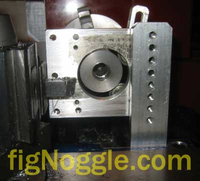
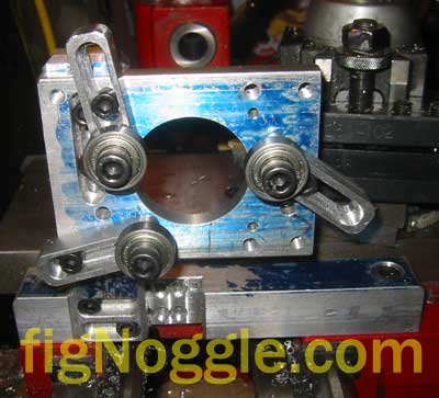
After all that work, you can see the tailstock view of the assembly with a piece of 1.5″ diameter steel rod used for the injection molding barrel/nozzle assembly inserted in the chuck and through the rest.

Note the holes in the post. This basically allows for a reasonable amount of “infinite” adjustability in the vertical direction.

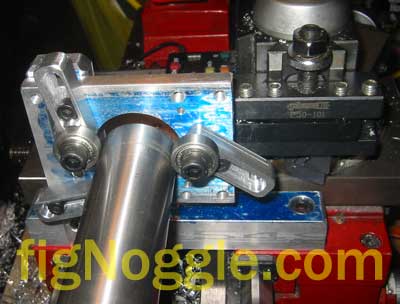
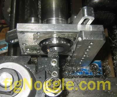
All that’s needed to make the hybrid steady/follow rest work is to generally position it such that the workpiece is centered in the plate. Then, adjust each of the fingers such that the bearings touch the circumference of the workpiece at roughly 120 degree points (360/3) and tighten down the socket head cap screws.

And a top view of the same:

Now, it’s time to test it!

The reason for this entire project was to be able to bore a larger diameter hole without causing the workpiece to runout from true. It works!

This project in total took about a half day of work. This is again a prototype and will definitely need some refinements. It does, however, serve its purpose. One problem encountered after some hard turning is that the grease in the ball bearings just about wore out. Perhaps a better bearing is the use of needle bearings which we had but would have required some more work. This will be the next modification to the design. The other advantage to using needle bearings is that they’re wider to begin with, thereby increasing the contact patch with the workpiece.

Stay tuned for more updates on this project.

‘,’

After the first day creating the “T” assembly of the hybrid follow/steady rest, we figure that the easiest way to complete this project (it’s just a prototype) is to quickly make a plate with a bored out circular hole to allow for the diameter of a larger workpiece and have the three “fingers” with attached ball bearings mount to this plate. Finally, the plate would be attached with slots for vertical mounting and adjustment to the “T” vertical post.

Luckily for us, we already had a plate with a bored hole that was one of the first prototypes of the X-axis NEMA 23 mounting plate for the X2 mini-mill CNC conversion. We still needed to bore the hole larger than the 1.5” or so that was already there.

One thing we keep forgetting to mention is the poor quality of the “dykem” marking paint (the blue you see) from ENCO. The problem with their brand of dye is that it doesn’t “stick” to the material and acts like the material has grease spots on it. Also, the can it comes in gets stuck after the first few uses. Very frustrating to use.

Back to the project…

We didn’t take “action shots” of the various pieces being milled. One point of interest is that while we’re having problems with the finish of workpieces using the Dayton/Grainger (aka RF-31) round column mill, boring operations have excellent finishes far superior than the X2 mini-mill. This indiciates to us that the quill indeed has some slop in it and will probably need its bearings regreased and adjusted.

Back to the project…

After drilling and tapping more 1/4” x 20 holes in the vertical post and milling slots in the plate, we also drilled and tapped a few holes for the 3 fingers. The 3 fingers are nothing more than some rounded-edges stock with slots in them for adjustability to the plate and a single 5/16” x 18tpi threaded hole for the ball bearing.

After all that work, you can see the tailstock view of the assembly with a piece of 1.5” diameter steel rod used for the injection molding barrel/nozzle assembly inserted in the chuck and through the rest.

Note the holes in the post. This basically allows for a reasonable amount of “infinite” adjustability in the vertical direction.

All that’s needed to make the hybrid steady/follow rest work is to generally position it such that the workpiece is centered in the plate. Then, adjust each of the fingers such that the bearings touch the circumference of the workpiece at roughly 120 degree points (360/3) and tighten down the socket head cap screws.

And a top view of the same:

Now, it’s time to test it!

The reason for this entire project was to be able to bore a larger diameter hole without causing the workpiece to runout from true. It works!

This project in total took about a half day of work. This is again a prototype and will definitely need some refinements. It does, however, serve its purpose. One problem encountered after some hard turning is that the grease in the ball bearings just about wore out. Perhaps a better bearing is the use of needle bearings which we had but would have required some more work. This will be the next modification to the design. The other advantage to using needle bearings is that they’re wider to begin with, thereby increasing the contact patch with the workpiece.

Stay tuned for more updates on this project.

‘,’After the first day creating the “T” assembly of the hybrid follow/steady rest, we figure that the easiest way to complete this project (it’s just a prototype) is to quickly make a plate with a bored out circular hole to allow for the diameter of a larger workpiece and have the three “fingers” with attached ball bearings mount to this plate. Finally, the plate would be attached with slots for vertical mounting and adjustment to the “T” vertical post.

‘,’

After the first day creating the “T” assembly of the hybrid follow/steady rest, we figure that the easiest way to complete this project (it’s just a prototype) is to quickly make a plate with a bored out circular hole to allow for the diameter of a larger workpiece and have the three “fingers” with attached ball bearings mount to this plate. Finally, the plate would be attached with slots for vertical mounting and adjustment to the “T” vertical post.

‘,”,’8x128x14-Small-Lathe’,”,1,’Comment’,0,4,1,1,’article’,”,”,’8x128x14-lathe-hybrid-follow-rest-moving-steady-rest-day-2′,”,”,”,”,”,”,”,”,”,”,’6b7f6a05ba134825c626e2da11b50cec’,’2007-02-04′);

8×12/8×14 Lathe Hybrid Follow Rest / Moving “Steady” Rest – Day 1

(268,’2007-02-04 22:49:59′,’david’,’2007-02-07 09:50:43′,’david’,’8×12/8×14 Lathe Hybrid Follow Rest / Moving “Steady” Rest – Day 1′,”,’One of the issues with the smaller lathes is the spindle bore diameter not being able to accomodate larger diameter workpieces of longer lengths for more secure chucking using the chuck.

This issue becomes more apparent when working with longer pieces that need to be bored, for example. In this scenario, using a face plate with lathe dog and a live center on the tailstock wouldn’t be appropriate. So what can we use?

A standard “steady rest” could very well work provided that it can be set in between the carriage and chuck and still provide adequate support. Another alternative is to use a “follow rest” which is somewhat similar to the steady rest with the primary difference that it is mounted to the carriage and therefore travels with it along the carriage’s travel.

The other issue when assessing these rests is there capacity. Since we’re working with larger diameter (relatively speaking) of 1.5″ diameter and larger, it is important that we make one ourselves that could handle these larger diameters.

About a year and half ago, we mentioned on one of the Yahoo! groups for mini-lathes that we wanted to make a rest using ball bearings instead of the standard brass finger style that’s commonly found.

The first day consisted of figuring out the requirements of the rest and the machining of the initial “T” assembly – the base and vertical post.

Firstly, we grabbed a piece of 1″x1″ aluminum scrap and laid it across the two set screws on the left side of the carriage. These are the mounting holes for the follow rest.

We had to mark the locations of the two oil holes and account for this by milling recesses so that the oil hole ball bearings aren’t pushed down by the base of the rest. BTW, our ultimate design resembles a steady rest but acts more like a follow rest by nature of it being attached to the carriage.

After marking out the hole locations, we tested the fit on the carriage. Perfect fit!

Now we need to mill out a recess for the vertical post and drill and tap a series of holes so that the vertical post can be adjusted:

Note in the above picture the use of the Keo brand deburring / countersink tools. These are very nice indeed.

Sorry, we didn’t take pictures of the vertical post being machined, but you’ll get a closer look at this in part 2 of this series.

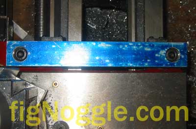
Here’s a snapshot of the vertical post mounted to the base making the “T”.

Note the recess for the vertical post and the series of holes for adjustment of the vertical post in the cross-slide direction (X).

Now comes the important part of the design. In common follow rests, the entire unit remains in a single plane. This does not allow for support of the workpiece in boring operations (not boring, boring :). Therefore, before making the fingers of the rest, we need to see how spacing would work for boring and general turning:

Note that with a boring bar in place, the follow rest would not even make contact with the workpiece, thereby rendering it useless.

With a standard left-cutting tool, the spacing should be fine.\r\nNow we have a general idea this rest actually needs to be offset towards the chuck in able to engage the workpiece prior to the cutter making contact.

And the final shot for the day of the “T” assembly from the tailstock point of view.

Read on for Part 2 of this project.\r\n’,’

One of the issues with the smaller lathes is the spindle bore diameter not being able to accomodate larger diameter workpieces of longer lengths for more secure chucking using the chuck.

This issue becomes more apparent when working with longer pieces that need to be bored, for example. In this scenario, using a face plate with lathe dog and a live center on the tailstock wouldn’t be appropriate. So what can we use?

A standard “steady rest” could very well work provided that it can be set in between the carriage and chuck and still provide adequate support. Another alternative is to use a “follow rest” which is somewhat similar to the steady rest with the primary difference that it is mounted to the carriage and therefore travels with it along the carriage’s travel.

The other issue when assessing these rests is there capacity. Since we’re working with larger diameter (relatively speaking) of 1.5” diameter and larger, it is important that we make one ourselves that could handle these larger diameters.

About a year and half ago, we mentioned on one of the Yahoo! groups for mini-lathes that we wanted to make a rest using ball bearings instead of the standard brass finger style that’s commonly found.

The first day consisted of figuring out the requirements of the rest and the machining of the initial “T” assembly – the base and vertical post.

Firstly, we grabbed a piece of 1“x1” aluminum scrap and laid it across the two set screws on the left side of the carriage. These are the mounting holes for the follow rest.

We had to mark the locations of the two oil holes and account for this by milling recesses so that the oil hole ball bearings aren’t pushed down by the base of the rest. BTW, our ultimate design resembles a steady rest but acts more like a follow rest by nature of it being attached to the carriage.

After marking out the hole locations, we tested the fit on the carriage. Perfect fit!

Now we need to mill out a recess for the vertical post and drill and tap a series of holes so that the vertical post can be adjusted:

Note in the above picture the use of the Keo brand deburring / countersink tools. These are very nice indeed.

Sorry, we didn’t take pictures of the vertical post being machined, but you’ll get a closer look at this in part 2 of this series.

Here’s a snapshot of the vertical post mounted to the base making the “T”.

Note the recess for the vertical post and the series of holes for adjustment of the vertical post in the cross-slide direction (X).

Now comes the important part of the design. In common follow rests, the entire unit remains in a single plane. This does not allow for support of the workpiece in boring operations (not boring, boring :). Therefore, before making the fingers of the rest, we need to see how spacing would work for boring and general turning:

Note that with a boring bar in place, the follow rest would not even make contact with the workpiece, thereby rendering it useless.

With a standard left-cutting tool, the spacing should be fine.
\nNow we have a general idea this rest actually needs to be offset towards the chuck in able to engage the workpiece prior to the cutter making contact.

And the final shot for the day of the “T” assembly from the tailstock point of view.

Read on for Part 2 of this project.

‘,’One of the issues with the smaller lathes is the spindle bore diameter not being able to accomodate larger diameter workpieces of longer lengths for more secure chucking using the chuck.

This issue becomes more apparent when working with longer pieces that need to be bored, for example. In this scenario, using a face plate with lathe dog and a live center on the tailstock wouldn’t be appropriate. So what can we use?

‘,’

One of the issues with the smaller lathes is the spindle bore diameter not being able to accomodate larger diameter workpieces of longer lengths for more secure chucking using the chuck.

This issue becomes more apparent when working with longer pieces that need to be bored, for example. In this scenario, using a face plate with lathe dog and a live center on the tailstock wouldn’t be appropriate. So what can we use?

‘,”,’8x128x14-Small-Lathe’,”,1,’Comment’,0,4,1,1,’article’,”,”,’8x128x14-lathe-hybrid-follow-rest-moving-steady-rest-day-1′,”,”,”,”,”,”,”,”,”,”,’7f6fae947afd6427bef0cfea3f0a881c’,’2007-02-04′);