(274,’2007-02-20 17:58:37′,’david’,’2007-02-20 18:06:47′,’david’,’Kurt D675 AngLock Vise Arrived!’,”,’We started machining small parts. As we moved onto larger machines and workpieces for making things for the small mini-machines making things for those machines (say that 10 times ![]() ), we needed to become more efficient in some operations. We’ve always been big fans of workholding techniques. Having a large vise is just part of that fascination.
), we needed to become more efficient in some operations. We’ve always been big fans of workholding techniques. Having a large vise is just part of that fascination.
When we moved onto the ever-popular round-column mill/drill with a table that rivals that of full-sized knee/turret mills (9″x32″ table to be exact), we were in need of a larger vise. The choice was simple – a 6″ wide vise that you commonly find in many machine shops. Instead of buying an import this time, we wanted to buy real American cast iron. The Kurt D675 was the obvious choice.
After checking out ENCO and few other catalogs, we found a good deal via eBay. Even with shipping charges, we were able to save some money.
A week later, the box arrived:
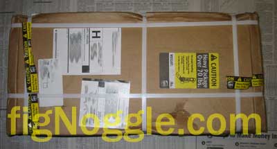
Another picture of the box (we promise to show something a bit more substantial in a few seconds):
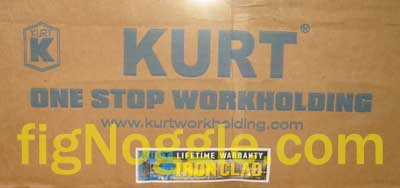
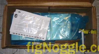
We opened up the box to find the warranty card, a bag containing two o-rings, and the 80 lb. vise.
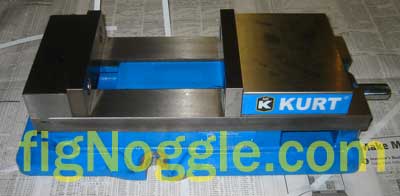
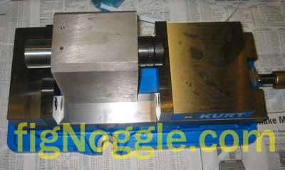
We then lug the vise out and get a glimpse of the massiveness of the vise:
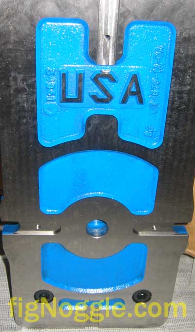
Flipping the vise over, we see a nice casting with a very prominent “USA” ground in:
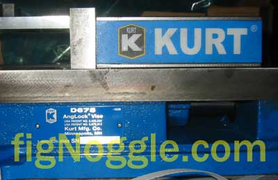
The size placard/nameplate and the “Kurt blue” says it all:
They also include what they call a “chip guard”. It’s merely a thin guage sheet steel that slides in between the channel to cover the innards of the vise from chips.
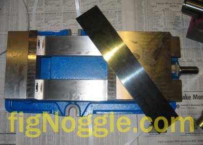
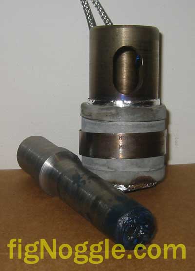
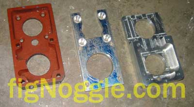
Just for scale, we’ve chucked in the X2 mini-mill belt drive conversion plate lengthwise in the vise:

And the spindle/head of the mini-mill is also placed in there. This is one very hefty piece of American cast iron, indeed!
We’ll post more pictures with this vise mounted in its new home and provide some tips and tricks in workholding at a later time.
In the meantime, you can read more about why we chose the D675 over the D688 and D810 from Kurt as well the Parlec PSW-6900 6″ vise.
Stay tuned…
‘,’
We started machining small parts. As we moved onto larger machines and workpieces for making things for the small mini-machines making things for those machines (say that 10 times ![]() ), we needed to become more efficient in some operations. We’ve always been big fans of workholding techniques. Having a large vise is just part of that fascination.
), we needed to become more efficient in some operations. We’ve always been big fans of workholding techniques. Having a large vise is just part of that fascination.
When we moved onto the ever-popular round-column mill/drill with a table that rivals that of full-sized knee/turret mills (9“x32” table to be exact), we were in need of a larger vise. The choice was simple – a 6” wide vise that you commonly find in many machine shops. Instead of buying an import this time, we wanted to buy real American cast iron. The Kurt D675 was the obvious choice.
After checking out ENCO and few other catalogs, we found a good deal via eBay. Even with shipping charges, we were able to save some money.
A week later, the box arrived:
Another picture of the box (we promise to show something a bit more substantial in a few seconds):
We opened up the box to find the warranty card, a bag containing two o-rings, and the 80 lb. vise.
We then lug the vise out and get a glimpse of the massiveness of the vise:
Flipping the vise over, we see a nice casting with a very prominent “USA” ground in:
The size placard/nameplate and the “Kurt blue” says it all:
They also include what they call a “chip guard”. It’s merely a thin guage sheet steel that slides in between the channel to cover the innards of the vise from chips.
Just for scale, we’ve chucked in the X2 mini-mill belt drive conversion plate lengthwise in the vise:
And the spindle/head of the mini-mill is also placed in there. This is one very hefty piece of American cast iron, indeed!
We’ll post more pictures with this vise mounted in its new home and provide some tips and tricks in workholding at a later time.
In the meantime, you can read more about why we chose the D675 over the D688 and D810 from Kurt as well the Parlec PSW-6900 6” vise.
Stay tuned…
‘,’We started machining small parts. As we moved onto larger machines and workpieces for making things for the small mini-machines making things for those machines (say that 10 times ![]() ), we needed to become more efficient in some operations. We’ve always been big fans of workholding techniques. Having a large vise is just part of that fascination.
), we needed to become more efficient in some operations. We’ve always been big fans of workholding techniques. Having a large vise is just part of that fascination.
When we moved onto the ever-popular round-column mill/drill with a table that rivals that of full-sized knee/turret mills (9″x32″ table to be exact), we were in need of a larger vise. The choice was simple – a 6″ wide vise that you commonly find in many machine shops. Instead of buying an import this time, we wanted to buy real American cast iron. The Kurt D675 was the obvious choice.
After checking out ENCO and few other catalogs, we found a good deal via eBay. Even with shipping charges, we were able to save some money.
A week later, the box arrived:
‘,’
We started machining small parts. As we moved onto larger machines and workpieces for making things for the small mini-machines making things for those machines (say that 10 times ![]() ), we needed to become more efficient in some operations. We’ve always been big fans of workholding techniques. Having a large vise is just part of that fascination.
), we needed to become more efficient in some operations. We’ve always been big fans of workholding techniques. Having a large vise is just part of that fascination.
When we moved onto the ever-popular round-column mill/drill with a table that rivals that of full-sized knee/turret mills (9“x32” table to be exact), we were in need of a larger vise. The choice was simple – a 6” wide vise that you commonly find in many machine shops. Instead of buying an import this time, we wanted to buy real American cast iron. The Kurt D675 was the obvious choice.
After checking out ENCO and few other catalogs, we found a good deal via eBay. Even with shipping charges, we were able to save some money.
A week later, the box arrived:
‘,”,”,”,1,’Comment’,0,4,1,1,’article’,”,”,’kurt-d675-anglock-vise-arrived’,”,”,”,”,”,”,”,”,”,”,’f05e3cb937f8cbc8c4c6f62e8186a370′,’2007-02-20′);