(254,’2006-10-13 12:00:00′,’figNoggle’,’2006-12-20 08:01:31′,’david’,’Fitting A Ball Screw To The 8″x12″ Lathe Cross Slide’,”,’Back to the 8×12 CNC project!
We know already that the saddle is going to get a ball screw that will be fitted close to the feed screw and mounted to the saddle. That’s the easy part.
One of the continuing challenges is trying to get these little machines (well, the 8×12 isn’t so little compared the 7×10/12/14 for example) to accept parts that we want to add in. Case in point: ballscrews in the X2 mini-mill.. We’ve done it, but it wasn’t without some major work given that we wanted to maintain travel and have the resulting benefits of a faster moving, more accurate machine all-around. But we digress..
We purchased a 12mm diameter C3 grade ball screw (it had a little play, so it may need to be reballed eventually) and immediately took off the cross slide to see how it would fit.

Initially it appeared that all we would need to do was to cut off one side of the flange and the other side would just fit in the existing hole that houses the cast iron lead nut (no kidding – cast iron!):
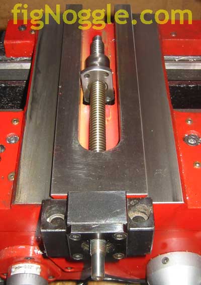
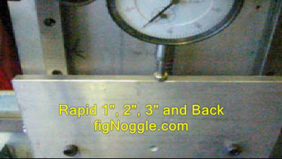
The ball nut housing fits just fine within the channel as you can see. You may have noticed that the ball screw is a bit short. If we were to have the ball nut placed here, the end resulting travel would only be 2″ or so. Not ideal but we’d like to semi-production turn screws and other things of less than 1.5″ diameter so that shouldn’t be a problem. If that weren’t enough of a constraint, after remounting the slide and putting the QCTP tooling on it mocked up to cut 1.5″ stock, we quickly realized that even that positioning wouldn’t work. At this point Murphy showed up and read some of his law to us:
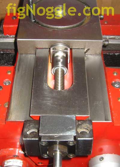
Yes, you see it. Clearly, it looked like the ball nut flange would have to be worked with some to get it to fit inside the channel of the carriage. This, in addition to the length issue led us to try some alternatives like mounting the screw on the other side of the slide.
At the end of all of this, it still looks like we may need to use our in-house 5/8″ dia. ball screw and mount the nut to the outside of the slide on the back side. This way, there wouldn’t be any issue with mounting the nut within the channel. This may just be the way to go. (Any one need a 12mm dia. C3 ball screw? :)’
‘,’
Back to the 8×12 CNC project!
We know already that the saddle is going to get a ball screw that will be fitted close to the feed screw and mounted to the saddle. That’s the easy part.
One of the continuing challenges is trying to get these little machines (well, the 8×12 isn’t so little compared the 7×10/12/14 for example) to accept parts that we want to add in. Case in point: ballscrews in the X2 mini-mill.. We’ve done it, but it wasn’t without some major work given that we wanted to maintain travel and have the resulting benefits of a faster moving, more accurate machine all-around. But we digress..
We purchased a 12mm diameter C3 grade ball screw (it had a little play, so it may need to be reballed eventually) and immediately took off the cross slide to see how it would fit.
Initially it appeared that all we would need to do was to cut off one side of the flange and the other side would just fit in the existing hole that houses the cast iron lead nut (no kidding – cast iron!):
The ball nut housing fits just fine within the channel as you can see. You may have noticed that the ball screw is a bit short. If we were to have the ball nut placed here, the end resulting travel would only be 2” or so. Not ideal but we’d like to semi-production turn screws and other things of less than 1.5” diameter so that shouldn’t be a problem. If that weren’t enough of a constraint, after remounting the slide and putting the QCTP tooling on it mocked up to cut 1.5” stock, we quickly realized that even that positioning wouldn’t work. At this point Murphy showed up and read some of his law to us:
Yes, you see it. Clearly, it looked like the ball nut flange would have to be worked with some to get it to fit inside the channel of the carriage. This, in addition to the length issue led us to try some alternatives like mounting the screw on the other side of the slide.
At the end of all of this, it still looks like we may need to use our in-house 5/8” dia. ball screw and mount the nut to the outside of the slide on the back side. This way, there wouldn’t be any issue with mounting the nut within the channel. This may just be the way to go. (Any one need a 12mm dia. C3 ball screw? :)’
‘,”,”,”,’8x128x14-Small-Lathe’,”,0,”,0,4,1,1,’article’,”,”,’fitting-a-ball-screw-to-the-8×12-lathe-cross-slide’,”,”,”,”,”,”,”,”,”,”,’8736e486cac8b7f4d8a7ec3c0812744d’,’2006-10-13′);
 ‘
‘