(251,’2006-10-04 12:00:00′,’figNoggle’,’2006-12-20 08:01:55′,’david’,’Photodarlington Optical Interrupter Switch Wiring How-To’,”,’Up until a last week, we had never hooked up a “optical switch” before for the purposes of home and limit switches which are commonly used in CNC applications since there is no mechanical contact involved and response times and accuracies are well suited for CNC.
Optical switches anyone?
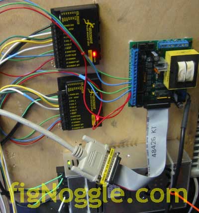
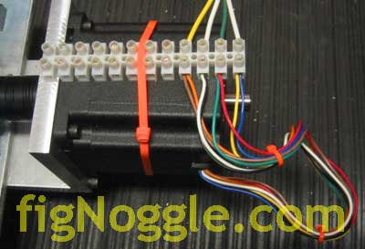
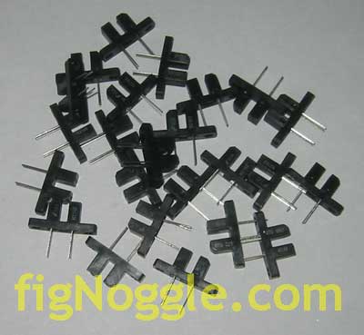
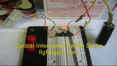
We had a few of these “photodarlington optical interrupter switches” laying around (not the picture above – this was taken after we thought we blew out the few we had and bought a bunch for good measure) and decided to test them out. Imagine our frustration when the wiring diagram provided in the manufacturers’ data sheets show how to wire them up and we couldn’t get them to work for the life of us! Frustration abound and hours (literally) “wasted”…
Let’s start with the basics.
In catalogs like Mouser, Digi-Key, and Jameco, a few options are offered. Since we shop at Jameco, we’ll talk about that one.
One brand offered is from IsoCom Components and the other is Fairchild Semiconductor (they still exist?) with the models H21A1/H21A2/H21A3 and H21B1/H21B2/H21B3 respectively. The differences come down to the output voltage requirements and collector currents (at least that what we can gather – reading these data sheets can make your head spin..).
We used a Fairchild H21B2 picked at random and hooked it up thinking that we had initially blown the other switch using a 12V 1A power supply. As it turns out it was fine but that’s another story.
After realizing that this is essentially a transistor with the collector and emitter on the right hand side and the base on the left (in this case instead of a pin, it’s an infrared diode), we looked around on how to wire one up. Up until this point we had asked around a few newsgroups and folks came to help but it still left us in the dark. So, imagine our surprise when it still didn’t “work”. We had a simple circuit that would light up a LED when the switch was in the ON state.
Anyhoo.. We ran a basic test with our $10 multimeter in diode mode. It shows a value “1” like a good meter would show a “OL” for overload and when there is a flow-through circuit would give you “0” ideally or some other value if there was resistance in the circuit.
Here’s how to test it. Hook up the diode side as a simple circuit and then the right side to a multimeter only and set the meter in diode mode. Make sure the polarity is correct and leave the power off:
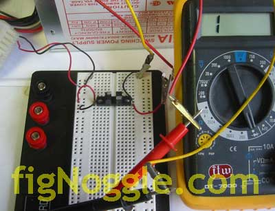
You should get something like that.
Then, turn the power on:
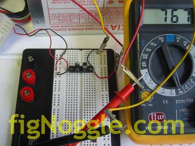
You should get some reading. This basically means that the C/E pins are “connected”. This means your switch works.
Now is where things got confusing until the “AHA” moment…
We had connected both sides of the switch using the same power supply. What we suspect happened here is that the diode had the least resistance and the current flowed through that one giving virtually no flow through the LED. Get ready for the “AHA” moment… (Drum roll please…..) Once we used separate power supplies for each side, it worked! Hallelujiah!
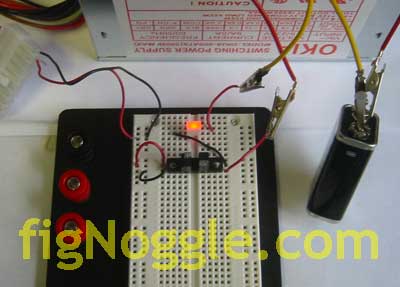
We’ve included a picture of it ON and OFF. Note the wiring in case you run into the same problems we did.
Here it is ON:
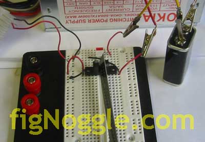
Now we put something in between the sides (in the slot) to interrupt the beam and it goes into the OFF state:
And here’s a video of it in action (click the picture the view the video):
We didn’t mean to make you sit through this whole thing to show you a rough diagram of how to wire things up:
That’s it!
If we made any incorrect statements above, please do leave a comment and let us know. Thanks!
Updates: There was an error with the previous diagram. It’s now been fixed and updated (thanks to those who pointed this out). Also, we had some help with some folks on getting this wired up correctly using a SINGLE PC power supply. Turns out we didn’t use “pull-down” resistors. One of the fellows was gracious enough to allow us to post his email reply to our request for help (thanks Manny!):
BEGIN
I suspect that the reason you needed 2 separate supplies is becasue you did not have a current limiting resistor in series with the photodiode portion of the sensor so it was dragging the voltage across the entire unit down to the forward voltage of the sensor, about 1.7 volts. This may be seen by the PC port as a constant LOW, never changing.Read on and try the following with 1 supply.
–
You should have some current limiting resistors in series with the photodiode and make sure there is enough resistance on the load (output side) to keep below the maximum collector current of the sensor.
For those that need to calculate this, its really easy. For the photodiode, look at the specs you will find a forward current and an operating voltage. in the case of the H21A1 we have 1.7Volts @ 0ma (milliamperes). If you hook it up to a 5v supply, this component will fail in short time.
To run it on a supply voltage greater than VF (Forward Voltge) you need to calculate a series current limiting resistance as follows: I will use 5 volts for an example.
IF (forward current) = .030
VFTITLE: Forward Voltage) = 1.7
VSTITLE: Supply Voltage)
R = resistance required
P = wattage of the resistor needed
R = (VS – VF)/ IF
R = 5-1.7/ .030
R= 110 Ohms
P = E x I (Where E is the Voltage to be dropped across the resistor (aka:VS-VF) and I = current through sensor)
P= 3.3 * 110
P= .099
So you would need a 110 Ohm resistor 1/10 Watt or higher in series with either lead to the photodiode.
—
For a 12Volt supply:
R = (12 -1.7) / .030
R = 343.333 Ohms
P= 10.3 * .030 = .309
So you should select a 343 Ohm 1/2Watt resistor for this supply voltage.
The resistance does not need to be exact so if oyu can’t find a 343 Ohm, you can use the next closest value higher which will, of course, give you a slight decrease in current allowed but shouldn’t pose any problems as long as you are still drawing about 25ma or better.
–
You can use the same formulas to calculate the load side but in most cases since you are just using the sensor to generate a signal on a pin, I would tie a 1K resistor from supply to collector, round the collector (NPN output) and take the sgnal form the collector/resistor junction. In an NPN-Collector configuration, this would give you a low when the sensor is open and a high when the sensor is blocked.
I hope some of you not so familiar with electronics find this handy. You can also look online for Ohms Law calculators to help compute these things.
END
Now, we should also say that there was a major problem with our understanding of these devices; we expected the LED to be ON when the slot is NOT interrupted. Turns out it’s vice-versa. Also, we had been using indicating devices like LEDs, buzzers, etc.. that required more voltage than, when our circuit was finally wired correctly, our circuit could output. Once these two things were worked out, it all made sense and the circuit worked!
Here’s the revised diagram showing how to use a single power supply. In this case it’s a 5VDC PC power supply:
Here’s what the circuit looked like in real life without the LED as the indicator. Note that the 1kohm and 1ohm resistors drop the voltage down to 2.8V:
And with the LED in place, it sucked another 1V:
And with the slot open i.e. NOT interrupted:
Finally, without the multimeter stuck in view with no obstruction in the slot. This would be an “active low” with basically an OFF state (as reversed logical as it may be to laymen like us):
Now, imagine your CNC machine moving and the interrupter device comes between the slot and interrupting the IR beam, you get an “active high” (ON state) telling the computer to do something (in this case, it’s the LED switching ON):
We hope this article brings some insight into how these photodarlington optical interrupter switches work. Watch in future installments as we connect this to our CNC vertical mill for limit/home switching purposes.
We want to again thank those who helped us get this working and we hope this helps others in the future.’ 16:22:5′);
‘,’
Up until a last week, we had never hooked up a “optical switch” before for the purposes of home and limit switches which are commonly used in CNC applications since there is no mechanical contact involved and response times and accuracies are well suited for CNC.
Optical switches anyone?
We had a few of these “photodarlington optical interrupter switches” laying around (not the picture above – this was taken after we thought we blew out the few we had and bought a bunch for good measure) and decided to test them out. Imagine our frustration when the wiring diagram provided in the manufacturers’ data sheets show how to wire them up and we couldn’t get them to work for the life of us! Frustration abound and hours (literally) “wasted”…
Let’s start with the basics.
In catalogs like Mouser, Digi-Key, and Jameco, a few options are offered. Since we shop at Jameco, we’ll talk about that one.
One brand offered is from IsoCom Components and the other is Fairchild Semiconductor (they still exist?) with the models H21A1/H21A2/H21A3 and H21B1/H21B2/H21B3 respectively. The differences come down to the output voltage requirements and collector currents (at least that what we can gather – reading these data sheets can make your head spin..).
We used a Fairchild H21B2 picked at random and hooked it up thinking that we had initially blown the other switch using a 12V 1A power supply. As it turns out it was fine but that’s another story.
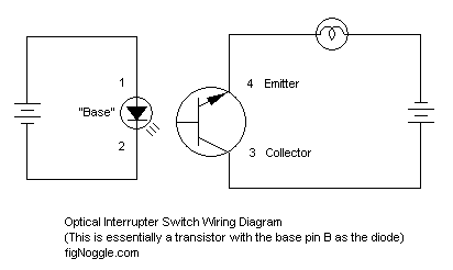
After realizing that this is essentially a transistor with the collector and emitter on the right hand side and the base on the left (in this case instead of a pin, it’s an infrared diode), we looked around on how to wire one up. Up until this point we had asked around a few newsgroups and folks came to help but it still left us in the dark. So, imagine our surprise when it still didn’t “work”. We had a simple circuit that would light up a LED when the switch was in the ON state.
Anyhoo.. We ran a basic test with our $10 multimeter in diode mode. It shows a value “1” like a good meter would show a “OL” for overload and when there is a flow-through circuit would give you “0” ideally or some other value if there was resistance in the circuit.
Here’s how to test it. Hook up the diode side as a simple circuit and then the right side to a multimeter only and set the meter in diode mode. Make sure the polarity is correct and leave the power off:
You should get something like that.
Then, turn the power on:
You should get some reading. This basically means that the C/E pins are “connected”. This means your switch works.
Now is where things got confusing until the “AHA” moment…
We had connected both sides of the switch using the same power supply. What we suspect happened here is that the diode had the least resistance and the current flowed through that one giving virtually no flow through the LED. Get ready for the “AHA” moment… (Drum roll please…..) Once we used separate power supplies for each side, it worked! Hallelujiah!
We’ve included a picture of it ON and OFF. Note the wiring in case you run into the same problems we did.
Here it is ON:
Now we put something in between the sides (in the slot) to interrupt the beam and it goes into the OFF state:
And here’s a video of it in action (click the picture the view the video):
We didn’t mean to make you sit through this whole thing to show you a rough diagram of how to wire things up:
That’s it!
If we made any incorrect statements above, please do leave a comment and let us know. Thanks!
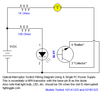
Updates: There was an error with the previous diagram. It’s now been fixed and updated (thanks to those who pointed this out). Also, we had some help with some folks on getting this wired up correctly using a SINGLE PC power supply. Turns out we didn’t use “pull-down” resistors. One of the fellows was gracious enough to allow us to post his email reply to our request for help (thanks Manny!):
BEGIN
I suspect that the reason you needed 2 separate supplies is becasue you did not have a current limiting resistor in series with the photodiode portion of the sensor so it was dragging the voltage across the entire unit down to the forward voltage of the sensor, about 1.7 volts. This may be seen by the PC port as a constant LOW, never changing.Read on and try the following with 1 supply.
—
You should have some current limiting resistors in series with the photodiode and make sure there is enough resistance on the load (output side) to keep below the maximum collector current of the sensor.
For those that need to calculate this, its really easy. For the photodiode, look at the specs you will find a forward current and an operating voltage. in the case of the H21A1 we have 1.7Volts @ 0ma (milliamperes). If you hook it up to a 5v supply, this component will fail in short time.
To run it on a supply voltage greater than VF (Forward Voltge) you need to calculate a series current limiting resistance as follows: I will use 5 volts for an example.
IF (forward current) = .030
VFTITLE: Forward Voltage) = 1.7
VSTITLE: Supply Voltage)
R = resistance required
P = wattage of the resistor needed
R = (VS – VF)/ IF
R = 5-1.7/ .030
R= 110 Ohms
P = E x I (Where E is the Voltage to be dropped across the resistor (aka:VS-VF) and I = current through sensor)
P= 3.3 * 110
P= .099
So you would need a 110 Ohm resistor 1/10 Watt or higher in series with either lead to the photodiode.
—-
For a 12Volt supply:
R = (12 -1.7) / .030
R = 343.333 Ohms
P= 10.3 * .030 = .309
So you should select a 343 Ohm 1/2Watt resistor for this supply voltage.
The resistance does not need to be exact so if oyu can’t find a 343 Ohm, you can use the next closest value higher which will, of course, give you a slight decrease in current allowed but shouldn’t pose any problems as long as you are still drawing about 25ma or better.
—
You can use the same formulas to calculate the load side but in most cases since you are just using the sensor to generate a signal on a pin, I would tie a 1K resistor from supply to collector, round the collector (NPN output) and take the sgnal form the collector/resistor junction. In an NPN-Collector configuration, this would give you a low when the sensor is open and a high when the sensor is blocked.
I hope some of you not so familiar with electronics find this handy. You can also look online for Ohms Law calculators to help compute these things.
END
Now, we should also say that there was a major problem with our understanding of these devices; we expected the LED to be ON when the slot is NOT interrupted. Turns out it’s vice-versa. Also, we had been using indicating devices like LEDs, buzzers, etc.. that required more voltage than, when our circuit was finally wired correctly, our circuit could output. Once these two things were worked out, it all made sense and the circuit worked!
Here’s the revised diagram showing how to use a single power supply. In this case it’s a 5VDC PC power supply:
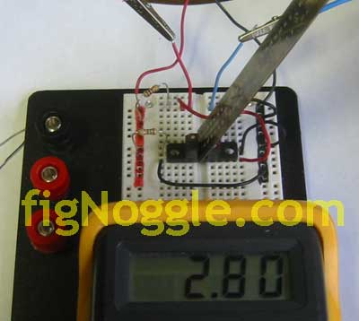
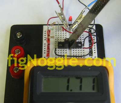
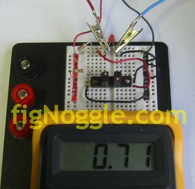
Here’s what the circuit looked like in real life without the LED as the indicator. Note that the 1kohm and 1ohm resistors drop the voltage down to 2.8V:
And with the LED in place, it sucked another 1V:
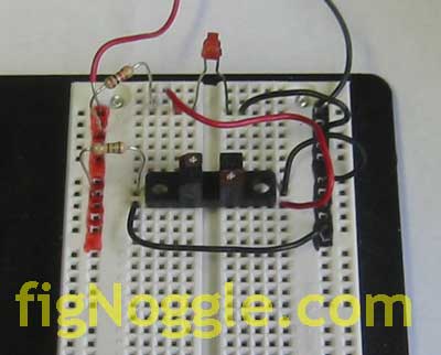
And with the slot open i.e. NOT interrupted:
Finally, without the multimeter stuck in view with no obstruction in the slot. This would be an “active low” with basically an OFF state (as reversed logical as it may be to laymen like us):
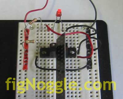
Now, imagine your CNC machine moving and the interrupter device comes between the slot and interrupting the IR beam, you get an “active high” (ON state) telling the computer to do something (in this case, it’s the LED switching ON):
We hope this article brings some insight into how these photodarlington optical interrupter switches work. Watch in future installments as we connect this to our CNC vertical mill for limit/home switching purposes.
We want to again thank those who helped us get this working and we hope this helps others in the future.’ 16:22:5’);
‘,”,”,”,’Home-Brewed-CNC-Vertical-Mill’,”,0,”,0,4,1,1,’article’,”,”,’photodarlington-optical-interrupter-switch-wiring-how-to’,”,”,”,”,”,”,”,”,”,”,’79c7035a4bb8b78c6948bb5bc230a117′,’2006-10-04′);