(237,’2006-08-04 12:00:00′,’figNoggle’,’2007-01-05 00:06:19′,’david’,’Broaching Keyways Using A Lathe’,”,’Thought this would be of interest to some of you who may want to make a keyway in a pulley or something like that. It had been asked in a few forums before and since there are only a few references online about how to do this, we thought we’d contribute!
This is for demonstration purposes only, so you may see a few details in this pictorial that are obviously not quite right. However, it should get the point across as to how to make those slots in pulleys using your 7×1 7×1 7×1 8×1 8×1 9×2 etc. mini-lathes.
We should first point out that there are such kits available for broaching keyways. They typically have a few long metal bars of various sizes and bushings that when inserted into the appropriately sized hole, provide just enough clearance to allow the metal bar to pass through and make cuts. The metal bars (picture coming soon) kind of look like what you’d get if you unwrapped the circumference of a circular saw blade. The teeth are different, but there are essentially a slightly sloped gradation of cutting teeth fixed to this bar.
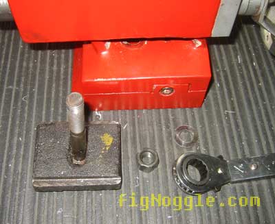
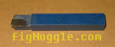
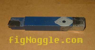
In this pictorial, we’ll just show a one-off version which is no more than a typical (non-insert) lathe toolbit. This one happens to be a 3/8″ bit size:
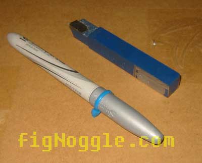
What we’re going to do is make some reliefs in the bit. Here’s the marked-up bit end (it’s the opposite side of the actual cutting end). BTW, these metal-colored “Sharpie” permanent markers make great markers for darker colored metals where the typical black ones wouldn’t show through:
After a few minutes of rough grinding with some 6 8 100 grit stones, we came up with this: (yes, it’s rough and not that sharp)
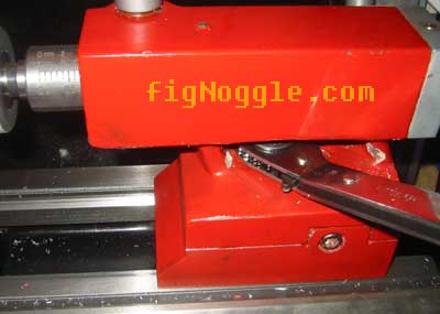
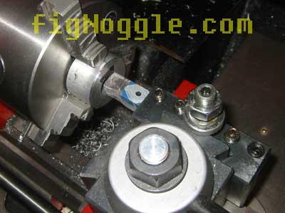
Now we get to the interesting part. Perhaps many people broach workpieces in the lathe with the keyway to be broached in a vertical orientation. What this means is that for broaching/cutting, you’d have to adjust the height of the toolbit for each pass. If you have a turret-style non-QCTP (like those that come stock with many mini-lathes), this means shimming in interations until you reach your depth of the keyway. What a pain! Here’s an example:
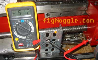
After sliding the carriage back and forth for each iteration of cut, then re-adjust the toolbit height, repeat, etc.. you end up with something like this:
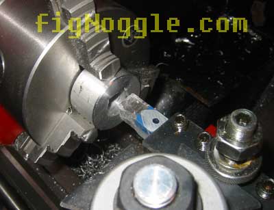
Again, this is for demonstration purposes only so we didn’t go all the way through or make a deep cut. One of the reasons is that the bit became dull quite quickly (and it didn’t help that it was dull to begin with!).
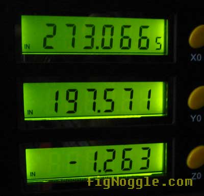
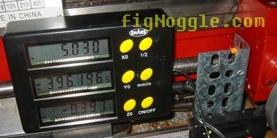
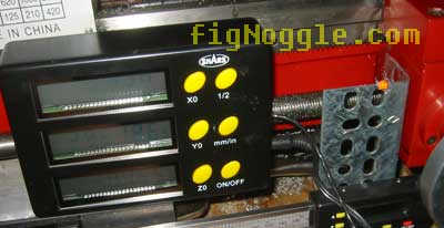
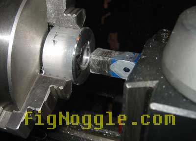
Now, the tip (if you will) here is that it’s somewhat easier (perhaps matter of opinion here) to adjust the depth of the keyway cuts by simply adjusting the depth of the cross feed! This means not only can you measure the depth of cuts with the handle indicators (or DRO :)), you only have to measure the height of the toolbit once! No successive shimming with non-QCTPs and no re-adjusting the heights of the toolbit period.
To do this, you simply rotate the toolbit and workpiece such that the keyway is now to be oriented horizontally:
That’s it! We think that this is a much simpler approach to one-off broaching of workpieces using the lathe.’
‘,’
Thought this would be of interest to some of you who may want to make a keyway in a pulley or something like that. It had been asked in a few forums before and since there are only a few references online about how to do this, we thought we’d contribute!
This is for demonstration purposes only, so you may see a few details in this pictorial that are obviously not quite right. However, it should get the point across as to how to make those slots in pulleys using your 7×1 7×1 7×1 8×1 8×1 9×2 etc. mini-lathes.
We should first point out that there are such kits available for broaching keyways. They typically have a few long metal bars of various sizes and bushings that when inserted into the appropriately sized hole, provide just enough clearance to allow the metal bar to pass through and make cuts. The metal bars (picture coming soon) kind of look like what you’d get if you unwrapped the circumference of a circular saw blade. The teeth are different, but there are essentially a slightly sloped gradation of cutting teeth fixed to this bar.
In this pictorial, we’ll just show a one-off version which is no more than a typical (non-insert) lathe toolbit. This one happens to be a 3/8” bit size:
What we’re going to do is make some reliefs in the bit. Here’s the marked-up bit end (it’s the opposite side of the actual cutting end). BTW, these metal-colored “Sharpie” permanent markers make great markers for darker colored metals where the typical black ones wouldn’t show through:
After a few minutes of rough grinding with some 6 8 100 grit stones, we came up with this: (yes, it’s rough and not that sharp)
Now we get to the interesting part. Perhaps many people broach workpieces in the lathe with the keyway to be broached in a vertical orientation. What this means is that for broaching/cutting, you’d have to adjust the height of the toolbit for each pass. If you have a turret-style non-QCTP (like those that come stock with many mini-lathes), this means shimming in interations until you reach your depth of the keyway. What a pain! Here’s an example:
After sliding the carriage back and forth for each iteration of cut, then re-adjust the toolbit height, repeat, etc.. you end up with something like this:
Again, this is for demonstration purposes only so we didn’t go all the way through or make a deep cut. One of the reasons is that the bit became dull quite quickly (and it didn’t help that it was dull to begin with!).
Now, the tip (if you will) here is that it’s somewhat easier (perhaps matter of opinion here) to adjust the depth of the keyway cuts by simply adjusting the depth of the cross feed! This means not only can you measure the depth of cuts with the handle indicators (or DRO :)), you only have to measure the height of the toolbit once! No successive shimming with non-QCTPs and no re-adjusting the heights of the toolbit period.
To do this, you simply rotate the toolbit and workpiece such that the keyway is now to be oriented horizontally:
That’s it! We think that this is a much simpler approach to one-off broaching of workpieces using the lathe.’
‘,’Thought this would be of interest to some of you who may want to make a keyway in a pulley or something like that. It had been asked in a few forums before and since there are only a few references online about how to do this, we thought we’d contribute!
This is for demonstration purposes only, so you may see a few details in this pictorial that are obviously not quite right. However, it should get the point across as to how to make those slots in pulleys using your 7×1 7×1 7×1 8×1 8×1 9×2 etc. mini-lathes.
‘,’
Thought this would be of interest to some of you who may want to make a keyway in a pulley or something like that. It had been asked in a few forums before and since there are only a few references online about how to do this, we thought we’d contribute!
This is for demonstration purposes only, so you may see a few details in this pictorial that are obviously not quite right. However, it should get the point across as to how to make those slots in pulleys using your 7×1 7×1 7×1 8×1 8×1 9×2 etc. mini-lathes.
‘,”,’8x128x14-Small-Lathe’,”,0,”,0,4,1,1,’article’,”,”,’broaching-keyways-using-a-lathe’,”,”,”,”,”,”,”,”,”,”,’5d48265c5ee0d360597d80a2c34159e5′,’2006-08-04′);