(268,’2007-02-04 22:49:59′,’david’,’2007-02-07 09:50:43′,’david’,’8×12/8×14 Lathe Hybrid Follow Rest / Moving “Steady” Rest – Day 1′,”,’One of the issues with the smaller lathes is the spindle bore diameter not being able to accomodate larger diameter workpieces of longer lengths for more secure chucking using the chuck.
This issue becomes more apparent when working with longer pieces that need to be bored, for example. In this scenario, using a face plate with lathe dog and a live center on the tailstock wouldn’t be appropriate. So what can we use?

A standard “steady rest” could very well work provided that it can be set in between the carriage and chuck and still provide adequate support. Another alternative is to use a “follow rest” which is somewhat similar to the steady rest with the primary difference that it is mounted to the carriage and therefore travels with it along the carriage’s travel.
The other issue when assessing these rests is there capacity. Since we’re working with larger diameter (relatively speaking) of 1.5″ diameter and larger, it is important that we make one ourselves that could handle these larger diameters.
About a year and half ago, we mentioned on one of the Yahoo! groups for mini-lathes that we wanted to make a rest using ball bearings instead of the standard brass finger style that’s commonly found.
The first day consisted of figuring out the requirements of the rest and the machining of the initial “T” assembly – the base and vertical post.
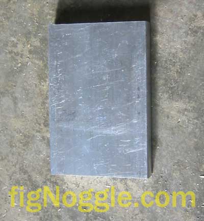
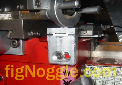
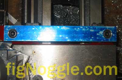
Firstly, we grabbed a piece of 1″x1″ aluminum scrap and laid it across the two set screws on the left side of the carriage. These are the mounting holes for the follow rest.

We had to mark the locations of the two oil holes and account for this by milling recesses so that the oil hole ball bearings aren’t pushed down by the base of the rest. BTW, our ultimate design resembles a steady rest but acts more like a follow rest by nature of it being attached to the carriage.
After marking out the hole locations, we tested the fit on the carriage. Perfect fit!
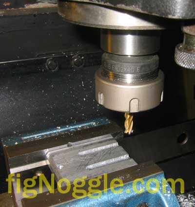
Now we need to mill out a recess for the vertical post and drill and tap a series of holes so that the vertical post can be adjusted:

Note in the above picture the use of the Keo brand deburring / countersink tools. These are very nice indeed.
Sorry, we didn’t take pictures of the vertical post being machined, but you’ll get a closer look at this in part 2 of this series.
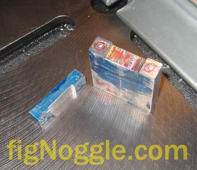
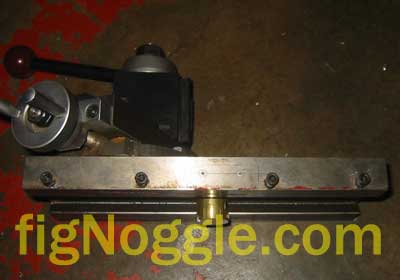
Here’s a snapshot of the vertical post mounted to the base making the “T”.

Note the recess for the vertical post and the series of holes for adjustment of the vertical post in the cross-slide direction (X).
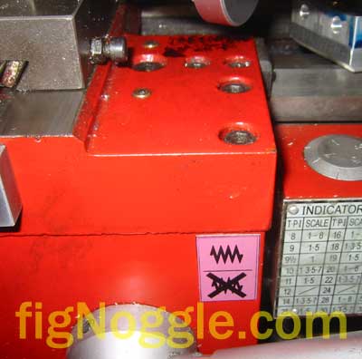
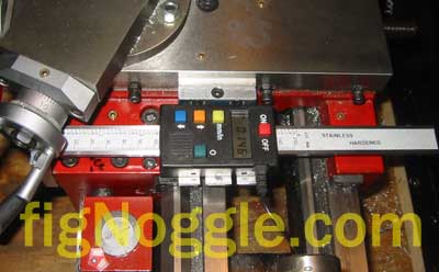
Now comes the important part of the design. In common follow rests, the entire unit remains in a single plane. This does not allow for support of the workpiece in boring operations (not boring, boring :). Therefore, before making the fingers of the rest, we need to see how spacing would work for boring and general turning:

Note that with a boring bar in place, the follow rest would not even make contact with the workpiece, thereby rendering it useless.

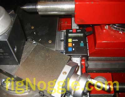
With a standard left-cutting tool, the spacing should be fine.\r\nNow we have a general idea this rest actually needs to be offset towards the chuck in able to engage the workpiece prior to the cutter making contact.
And the final shot for the day of the “T” assembly from the tailstock point of view.

Read on for Part 2 of this project.\r\n’,’
One of the issues with the smaller lathes is the spindle bore diameter not being able to accomodate larger diameter workpieces of longer lengths for more secure chucking using the chuck.
This issue becomes more apparent when working with longer pieces that need to be bored, for example. In this scenario, using a face plate with lathe dog and a live center on the tailstock wouldn’t be appropriate. So what can we use?
A standard “steady rest” could very well work provided that it can be set in between the carriage and chuck and still provide adequate support. Another alternative is to use a “follow rest” which is somewhat similar to the steady rest with the primary difference that it is mounted to the carriage and therefore travels with it along the carriage’s travel.
The other issue when assessing these rests is there capacity. Since we’re working with larger diameter (relatively speaking) of 1.5” diameter and larger, it is important that we make one ourselves that could handle these larger diameters.
About a year and half ago, we mentioned on one of the Yahoo! groups for mini-lathes that we wanted to make a rest using ball bearings instead of the standard brass finger style that’s commonly found.
The first day consisted of figuring out the requirements of the rest and the machining of the initial “T” assembly – the base and vertical post.
Firstly, we grabbed a piece of 1“x1” aluminum scrap and laid it across the two set screws on the left side of the carriage. These are the mounting holes for the follow rest.
We had to mark the locations of the two oil holes and account for this by milling recesses so that the oil hole ball bearings aren’t pushed down by the base of the rest. BTW, our ultimate design resembles a steady rest but acts more like a follow rest by nature of it being attached to the carriage.
After marking out the hole locations, we tested the fit on the carriage. Perfect fit!
Now we need to mill out a recess for the vertical post and drill and tap a series of holes so that the vertical post can be adjusted:
Note in the above picture the use of the Keo brand deburring / countersink tools. These are very nice indeed.
Sorry, we didn’t take pictures of the vertical post being machined, but you’ll get a closer look at this in part 2 of this series.
Here’s a snapshot of the vertical post mounted to the base making the “T”.
Note the recess for the vertical post and the series of holes for adjustment of the vertical post in the cross-slide direction (X).
Now comes the important part of the design. In common follow rests, the entire unit remains in a single plane. This does not allow for support of the workpiece in boring operations (not boring, boring :). Therefore, before making the fingers of the rest, we need to see how spacing would work for boring and general turning:
Note that with a boring bar in place, the follow rest would not even make contact with the workpiece, thereby rendering it useless.
With a standard left-cutting tool, the spacing should be fine.
\nNow we have a general idea this rest actually needs to be offset towards the chuck in able to engage the workpiece prior to the cutter making contact.
And the final shot for the day of the “T” assembly from the tailstock point of view.
Read on for Part 2 of this project.
‘,’One of the issues with the smaller lathes is the spindle bore diameter not being able to accomodate larger diameter workpieces of longer lengths for more secure chucking using the chuck.
This issue becomes more apparent when working with longer pieces that need to be bored, for example. In this scenario, using a face plate with lathe dog and a live center on the tailstock wouldn’t be appropriate. So what can we use?
‘,’
One of the issues with the smaller lathes is the spindle bore diameter not being able to accomodate larger diameter workpieces of longer lengths for more secure chucking using the chuck.
This issue becomes more apparent when working with longer pieces that need to be bored, for example. In this scenario, using a face plate with lathe dog and a live center on the tailstock wouldn’t be appropriate. So what can we use?
‘,”,’8x128x14-Small-Lathe’,”,1,’Comment’,0,4,1,1,’article’,”,”,’8x128x14-lathe-hybrid-follow-rest-moving-steady-rest-day-1′,”,”,”,”,”,”,”,”,”,”,’7f6fae947afd6427bef0cfea3f0a881c’,’2007-02-04′);