(262,’2006-12-25 22:45:36′,’david’,’2006-12-25 23:47:13′,’david’,’How To Remove The Harbor Freight 8″x12″ Or Lathemaster 8″x14″ Motor And Wiring Harness’,”,’Sooner or later you may have the need or desire to remove the motor from the 8x lathe.
In our case, we wanted to take some dimensions as well as move the lathe so it was time to tear this part of the lathe down. From an earlier procedure of tightening the sync belt, we found that while this lathe is quite robust for its price, many of its components are quite simply installed. This is quite good news for the DIY hobbyist who needs to make repairs in house.

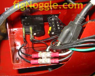
From the picture above, you can see that the wiring from the motor goes through the 18-20 gauge sheet metal enclosure and is terminated with spade terminals. It was easier to just remove the entire switch and wiring harness assembly…
The motor itself weighs in at over 10 lbs. It’s quite heavy.
Before we go too far into the procedure, here’s a reading from the motor. We are going to install a VFD (variable frequency drive) motor and control so that we can not only eliminate the pulley setup and get the pulleys removed, we can make speed changes at the twist of a knob).
The label:
Single Phase A.C. Induction Motor
Type YCYS7144A
550 W
110V
8.8 A
1700 RPM
60 Hz
IP44
300 uF
35 uF
E
S1

Onto the procedure..
You first remove the metal plate that covers the inside wiring of the switches. It’s only four metric socket head cap screws. Here’s the inside shot of the wiring:
Then you’ll need to remove the three philips head screws that hold the half enclosure that mounts to the lathe bed and the backplate of the pulley mount.

Now it’s time to remove the motor. There are four hex head bolts. Three of the four are easy to remove. The one located at the bottom left corner (facing the motor) is the most difficult due to its position to the table where it sits and that the motor is so close to to the bed. We had to prop up the lathe using two 2″x4″s to get it high enough off the table to access that bolt. Once removed, you see this:

The entire motor and wiring harness is shown here:
That’s it!
But.. if you’re planning on moving the lathe around, it’s best to also remove the backplate that holds the tension pulley and timing belt/intermediate gear in place. It’s held in place with two hex bolts. Remove those and you can now easily handle the lathe. It’s still pretty heavy, but it won’t be as difficult to manage.
Hope this helps!’,’
Sooner or later you may have the need or desire to remove the motor from the 8x lathe.
In our case, we wanted to take some dimensions as well as move the lathe so it was time to tear this part of the lathe down. From an earlier procedure of tightening the sync belt, we found that while this lathe is quite robust for its price, many of its components are quite simply installed. This is quite good news for the DIY hobbyist who needs to make repairs in house.
From the picture above, you can see that the wiring from the motor goes through the 18-20 gauge sheet metal enclosure and is terminated with spade terminals. It was easier to just remove the entire switch and wiring harness assembly…
The motor itself weighs in at over 10 lbs. It’s quite heavy.
Before we go too far into the procedure, here’s a reading from the motor. We are going to install a VFD (variable frequency drive) motor and control so that we can not only eliminate the pulley setup and get the pulleys removed, we can make speed changes at the twist of a knob).
The label:
Single Phase A.C. Induction Motor
Type YCYS7144A
550 W
110V
8.8 A
1700 RPM
60 Hz
IP44
300 uF
35 uF
E
S1
Onto the procedure..
You first remove the metal plate that covers the inside wiring of the switches. It’s only four metric socket head cap screws. Here’s the inside shot of the wiring:
Then you’ll need to remove the three philips head screws that hold the half enclosure that mounts to the lathe bed and the backplate of the pulley mount.
Now it’s time to remove the motor. There are four hex head bolts. Three of the four are easy to remove. The one located at the bottom left corner (facing the motor) is the most difficult due to its position to the table where it sits and that the motor is so close to to the bed. We had to prop up the lathe using two 2“x4“s to get it high enough off the table to access that bolt. Once removed, you see this:
The entire motor and wiring harness is shown here:
That’s it!
But.. if you’re planning on moving the lathe around, it’s best to also remove the backplate that holds the tension pulley and timing belt/intermediate gear in place. It’s held in place with two hex bolts. Remove those and you can now easily handle the lathe. It’s still pretty heavy, but it won’t be as difficult to manage.
Hope this helps!
‘,’Sooner or later you may have the need or desire to remove the motor from the 8x motor.
In our case, we wanted to take some dimensions as well as move the lathe so it was time to tear this part of the lathe down. From an earlier procedure of tightening the sync belt, we found that while this lathe is quite robust for its price, many of its components are quite simply installed. This is quite good news for the DIY hobbyist who needs to make repairs in house.
‘,’
Sooner or later you may have the need or desire to remove the motor from the 8x motor.
In our case, we wanted to take some dimensions as well as move the lathe so it was time to tear this part of the lathe down. From an earlier procedure of tightening the sync belt, we found that while this lathe is quite robust for its price, many of its components are quite simply installed. This is quite good news for the DIY hobbyist who needs to make repairs in house.
‘,”,’8x128x14-Small-Lathe’,”,1,’Comment’,0,4,1,1,’article’,”,”,’how-to-remove-the-harbor-freight-8×12-or-lathemaster-8×14-motor-and-wiring-harness’,”,”,”,”,”,”,”,”,”,”,’06425ab65af8928ce21b88660a8e82bf’,’2006-12-25′);