(247,’2006-09-22 12:00:00′,’figNoggle’,’2006-12-20 08:02:29′,’david’,’Making The X-Axis Combination NEMA 23 / NEMA 34 Motor Mount’,”,’If you’ve already seen the X/Y axis tests, that was the end result after having gone through some of the steps that we’re showing here.
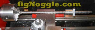
The X axis had been tested using a single reballed 5/8″x5TPI ballnut with oversized balls and an inexpensive rolled ballscrew.
But first we needed to make the motor mount for the X axis. What we’ve decided to do was to use the CNC X2 mini-mill (our plans work great!) to make a combo NEMA 23/34 motor mount for flexibility’s sake.
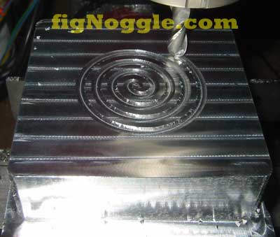
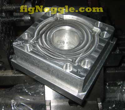
Step 1. Using the pocket from inside to outside, we start with a ball end mill. We really should have taken that extra step and drilled a hole in the center..
Step 2. Well, we’ve run the machine too hard and forgot to re-adjust the Y-axis for backlash. The result is the dreaded “egg”.
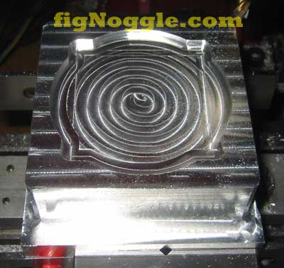
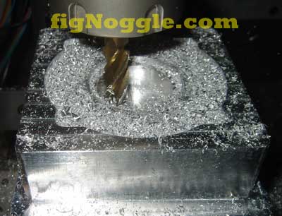
Step 3. After re-adjusting the nut, we started with the pockets again and then ended up boring the hole through:
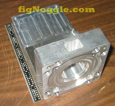
And voila! The motor mount side is completed.
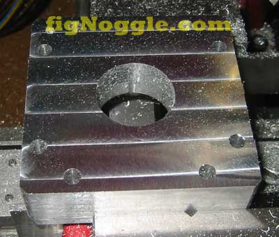
Since this started out as a large chunk of metal, we actually had to face the other side.. After a few minutes, it was faced to the thickness we wanted:
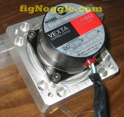
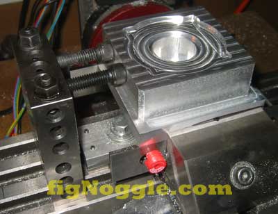
Now that that’s done (we also milled a pocket for access to the motor shaft), we do a test fit with a NEMA 34 frame step motor:
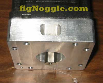
And to make sure a NEMA 23 frame motor also works, we mounted one for good measure. Looks like it’ll work!
We also had to mill the base that mounts to the X-axis “bed” and the mount. after a few simple facing, drilling and tapping operations, we put the two pieces together. We want to again point out that this is all done with the CNC’d X2 mini-mill. Like we’ve been saying all along, it’s quite a capable little machine!
We also want to point out the flexibility of 1-2-3 blocks for use as a work stop. We’ve built two of them up to match the height of the motor mount being machined so that we can take it out of the vise and re-insert without losing position:
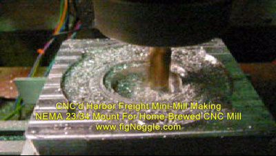
OK, now we all like watching videos of CNC in action, right? Well, here’s the X2 mini-mill making the pockets for the motor mount. Click on the picture to play the video. Don’t remember what speed it’s moving, but it’s taking a .02″ depth of cut (DOC) with a 1/2″ 4-flute carbide end mill running at something over 000 rpms. It was pretty quiet since we had our belt drive installed ![]()
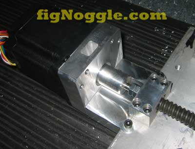
Finally, after all that work and making a solid shaft coupling (not recommended, btw), we assembly the X-axis motor setup:
Now, on to the Y-axis where we’ll use a grade C1 ballscrew from THK with a preloaded nut. Absolutely ZERO backlash. No more “eggs” folks!
Watch as we make the Y-axis bearing block, end mount, and ball nut flange.’
‘,’
If you’ve already seen the X/Y axis tests, that was the end result after having gone through some of the steps that we’re showing here.
The X axis had been tested using a single reballed 5/8“x5TPI ballnut with oversized balls and an inexpensive rolled ballscrew.
But first we needed to make the motor mount for the X axis. What we’ve decided to do was to use the CNC X2 mini-mill (our plans work great!) to make a combo NEMA 23/34 motor mount for flexibility’s sake.
Step 1. Using the pocket from inside to outside, we start with a ball end mill. We really should have taken that extra step and drilled a hole in the center..
Step 2. Well, we’ve run the machine too hard and forgot to re-adjust the Y-axis for backlash. The result is the dreaded “egg”.
Step 3. After re-adjusting the nut, we started with the pockets again and then ended up boring the hole through:
And voila! The motor mount side is completed.
Since this started out as a large chunk of metal, we actually had to face the other side.. After a few minutes, it was faced to the thickness we wanted:
Now that that’s done (we also milled a pocket for access to the motor shaft), we do a test fit with a NEMA 34 frame step motor:
And to make sure a NEMA 23 frame motor also works, we mounted one for good measure. Looks like it’ll work!
We also had to mill the base that mounts to the X-axis “bed” and the mount. after a few simple facing, drilling and tapping operations, we put the two pieces together. We want to again point out that this is all done with the CNC’d X2 mini-mill. Like we’ve been saying all along, it’s quite a capable little machine!
We also want to point out the flexibility of 1-2-3 blocks for use as a work stop. We’ve built two of them up to match the height of the motor mount being machined so that we can take it out of the vise and re-insert without losing position:
OK, now we all like watching videos of CNC in action, right? Well, here’s the X2 mini-mill making the pockets for the motor mount. Click on the picture to play the video. Don’t remember what speed it’s moving, but it’s taking a .02” depth of cut (DOC) with a 1/2” 4-flute carbide end mill running at something over 000 rpms. It was pretty quiet since we had our belt drive installed ![]()
Finally, after all that work and making a solid shaft coupling (not recommended, btw), we assembly the X-axis motor setup:
Now, on to the Y-axis where we’ll use a grade C1 ballscrew from THK with a preloaded nut. Absolutely ZERO backlash. No more “eggs” folks!
Watch as we make the Y-axis bearing block, end mount, and ball nut flange.’
‘,”,”,”,’Home-Brewed-CNC-Vertical-Mill’,”,0,”,0,4,1,1,’article’,”,”,’making-the-x-axis-combination-nema-23-nema-34-motor-mount’,”,”,”,”,”,”,”,”,”,”,’9d6271efd6481733610cbb4c8de8b782′,’2006-09-22′);