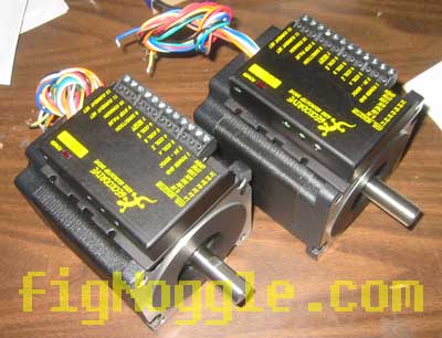
(240,’2006-08-15 12:00:00′,’figNoggle’,’2007-02-11 22:34:47′,’david’,’Sieg X2 Mini-Mill Belt Drive Conversion – Part 2′,”,’After waiting over the weekend for some cutting tools from ENCO (metric drill bit set and some square HSS tool bits for cutting the 5mm keyway on the spindle pulley), we resumed mocking up this prototype belt drive conversion.
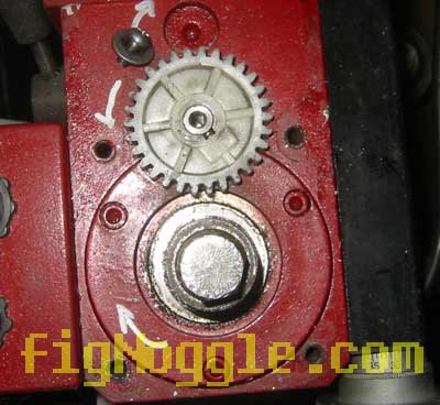
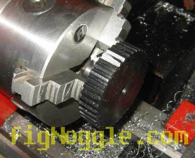
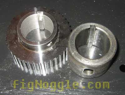
We wanted to make things interesting. How long would it take to work on these parts for the conversion while the drivetrain was disassembled? As it turns out, for roughing, it’s still quite fast. What took some time was cutting the keyway on the steel timing pulley for the spindle. After a few hours of machine work, you end up with something like this:
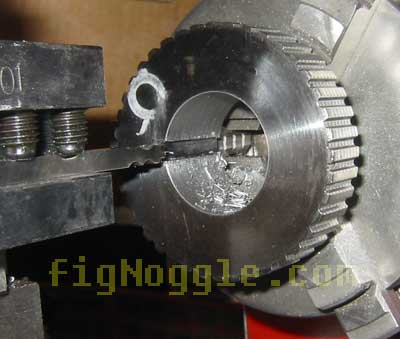
After quickly grinding down some multiple reliefs in the 3/16″ square tool bit, we got to work cutting the keyway in the timing pulley to the 8×12 lathe and eyeballed center after first placing the spindle collar on top of the pulley and scribing the location and depth of the keyway to be cut:
We could have purchased a $5 5mm bit from MSC Direct or other sources, but 3/16″ is close enough and would just require adjusting the height of the toolpost or some final skim passes to widen the keyway. Oh, the 3/16″ bits are just $0.49 each!
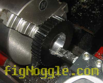
This took just over two hours to cut as we experimented with rotating the toolpost to increase the cutting relief angle of the bit. On smaller bits like this, deflection of the bit is common. One trick is to start with just a nub cut of less than 1/2″ or so to get things started. Then when you get close to the depth of cut, start extending the bit further for the full pass through. There will still be deflection, but it seems to work well. Also, when making cuts using a bit of the same width, the stock that isn’t ground with relief will rub against the keyway as the bit cuts through. The trick here is to rotate the toolpost so that only the cutting edges make contact with the keyway.
After many, many passes (CNC would be good here!), we end up with this:
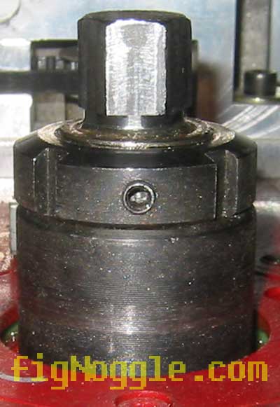
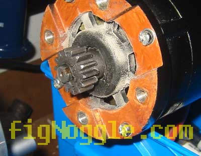
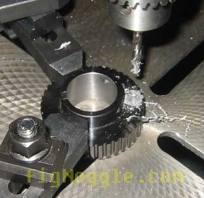
Now it’s time to drill a hole for the spindle lock. Remember in the previous stage we mentioned orienting the hole vertically. With a 8mm drill bit, a hole was drilled in the timing pulley:
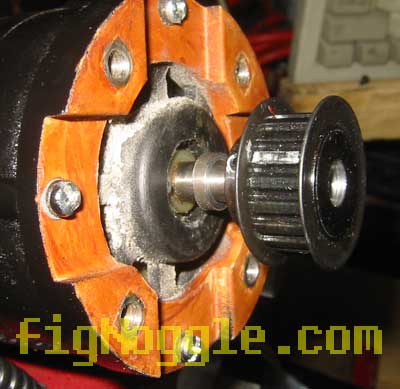
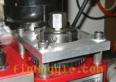
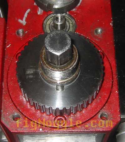
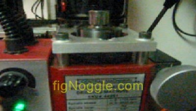
And here’s the pulley on the spindle:
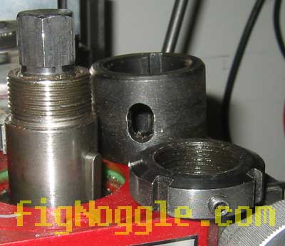
Next we need to offset the motor plate from the top of the spindle head. We had some steel tubing with the right hole diameter for the 6Mx1 metric socket head cap screws. This took a few minutes to part in the 8×12:
![]()
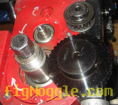
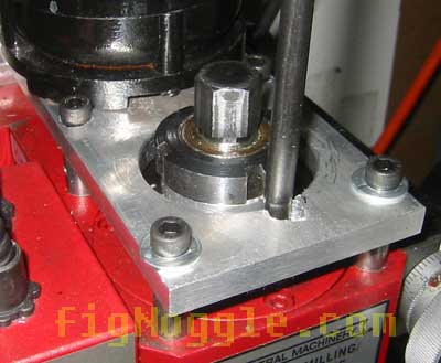
And here’s the assembly:
Oops! Forgot to drill the hole for the spindle lock. Just for kicks, a 5/16″ 2 flute end mill at 300rpm was used to attempt to “drill” the hole. OK, this is perhaps one of the uglier pictures you’ll see:
It was a mess.The spindle on the drill press wobbled like crazy and ultimately a combination of the end mill and drill bit were used.
Now, the moment our ears have been waiting for…
TITLE: Click on the image to view the short video clip. Now that’s music to our ears.)
The motor was spinning at max (based on rating) of 000rpm and with a 1:2 ratio, the spindle maxed at 000rpm. It’s noticably quiter than before!
BTW, the gear assembly in the head was adjusted with the lever so that they weren’t engaged. The “proper” way to do this is to remove the assembly which requires removing the head to access the cavity where they reside. Doing so prevents any chance you hit the lever and crunch the gearbox.
Now off to endurance testing… Some modifications will of course be made to the design, but in essence this was a really simple build requiring only a lathe and drill press which means you could do this while your mill was apart. Considering the cost of parts was under $50 (actually closer to $30+) and required minimal machining, it makes for a fun weekend upgrade. We’ll be offering plans and possibly kits) of this in the near future. Stay tuned…’
Here’s Version 2 of the prototype!’,’
After waiting over the weekend for some cutting tools from ENCO (metric drill bit set and some square HSS tool bits for cutting the 5mm keyway on the spindle pulley), we resumed mocking up this prototype belt drive conversion.
We wanted to make things interesting. How long would it take to work on these parts for the conversion while the drivetrain was disassembled? As it turns out, for roughing, it’s still quite fast. What took some time was cutting the keyway on the steel timing pulley for the spindle. After a few hours of machine work, you end up with something like this:
After quickly grinding down some multiple reliefs in the 3/16” square tool bit, we got to work cutting the keyway in the timing pulley to the 8×12 lathe and eyeballed center after first placing the spindle collar on top of the pulley and scribing the location and depth of the keyway to be cut:
We could have purchased a $5 5mm bit from MSC Direct or other sources, but 3/16” is close enough and would just require adjusting the height of the toolpost or some final skim passes to widen the keyway. Oh, the 3/16” bits are just $0.49 each!
This took just over two hours to cut as we experimented with rotating the toolpost to increase the cutting relief angle of the bit. On smaller bits like this, deflection of the bit is common. One trick is to start with just a nub cut of less than 1/2” or so to get things started. Then when you get close to the depth of cut, start extending the bit further for the full pass through. There will still be deflection, but it seems to work well. Also, when making cuts using a bit of the same width, the stock that isn’t ground with relief will rub against the keyway as the bit cuts through. The trick here is to rotate the toolpost so that only the cutting edges make contact with the keyway.
After many, many passes (CNC would be good here!), we end up with this:
Now it’s time to drill a hole for the spindle lock. Remember in the previous stage we mentioned orienting the hole vertically. With a 8mm drill bit, a hole was drilled in the timing pulley:
And here’s the pulley on the spindle:
Next we need to offset the motor plate from the top of the spindle head. We had some steel tubing with the right hole diameter for the 6Mx1 metric socket head cap screws. This took a few minutes to part in the 8×12:
![]()
And here’s the assembly:
Oops! Forgot to drill the hole for the spindle lock. Just for kicks, a 5/16” 2 flute end mill at 300rpm was used to attempt to “drill” the hole. OK, this is perhaps one of the uglier pictures you’ll see:
It was a mess.The spindle on the drill press wobbled like crazy and ultimately a combination of the end mill and drill bit were used.
Now, the moment our ears have been waiting for…
TITLE: Click on the image to view the short video clip. Now that’s music to our ears.)
The motor was spinning at max (based on rating) of 000rpm and with a 1:2 ratio, the spindle maxed at 000rpm. It’s noticably quiter than before!
BTW, the gear assembly in the head was adjusted with the lever so that they weren’t engaged. The “proper” way to do this is to remove the assembly which requires removing the head to access the cavity where they reside. Doing so prevents any chance you hit the lever and crunch the gearbox.
Now off to endurance testing… Some modifications will of course be made to the design, but in essence this was a really simple build requiring only a lathe and drill press which means you could do this while your mill was apart. Considering the cost of parts was under $50 (actually closer to $30+) and required minimal machining, it makes for a fun weekend upgrade. We’ll be offering plans and possibly kits) of this in the near future. Stay tuned…’
Here’s Version 2 of the prototype!
‘,’After waiting over the weekend for some cutting tools from ENCO (metric drill bit set and some square HSS tool bits for cutting the 5mm keyway on the spindle pulley), we resumed mocking up this prototype belt drive conversion.
We wanted to make things interesting. How long would it take to work on these parts for the conversion while the drivetrain was disassembled? As it turns out, for roughing, it’s still quite fast. What took some time was cutting the keyway on the steel timing pulley for the spindle. After a few hours of machine work, you end up with something like this:
<','
After waiting over the weekend for some cutting tools from ENCO (metric drill bit set and some square HSS tool bits for cutting the 5mm keyway on the spindle pulley), we resumed mocking up this prototype belt drive conversion.
We wanted to make things interesting. How long would it take to work on these parts for the conversion while the drivetrain was disassembled? As it turns out, for roughing, it’s still quite fast. What took some time was cutting the keyway on the steel timing pulley for the spindle. After a few hours of machine work, you end up with something like this:
<
‘,”,’Sieg-X2-Mini-Mill’,”,0,”,0,4,1,1,’article’,”,”,’sieg-x2-mini-mill-belt-drive-conversion-part-2′,”,”,”,”,”,”,”,”,”,”,’82359f039b0a6e65b37fee456b456e66′,’2006-08-15′);