(267,’2007-01-29 00:23:28′,’david’,’2007-01-29 01:03:56′,’david’,’8×12/14 Lathe X-Axis (Cross Slide) DRO Mounted!’,”,’Finally! We mocked up and made a working prototype of the 8×12/14 cross slide (X-Axis) DRO scale mounting brackets.

We knew going into this project that making this work would take some very finite positioning or extending the scale far back from the lathe to make things work. Since space is limited on these mini and small sized lathes, positioning and usability is everything. In doing so, we sacrificed an inch or so of distance between the carriage and tailstock. Our design goal was to make the scale readable without an external readout box just in case people didn’t want to spend $200 for one. Also, using a vertically-oriented scale took up more space than a horizontal version of the same length. Using a horizontal one would save more space yet, but would require that you rotate your head to read the scale for cross-slide movement.
So, it was decided that in order to make things somwhat user-friendly, the scale should not interfere with gib set screw adjustment, carriage lock set screw (it’s the larger sized screw to the right of the cross slide), and should not extend far beyond the foot print of the lathe itself. Again, the sacrifice would be the distance that the tailstock would usually have as it reaches the carriage (rather the tailstock would no longer be able to come right up against the carriage)…
Making the pieces for this came from a single piece of 6061-T6 aluminum bar stock 3/8″ thick and 2″ wide. The total materials cost was less than $5.
From this, we first milled the front end bracket:
This piece holds one end of the scale to the carriage.
Next, we milled the scale readout bracket and spacer block. We used the ER-32 collet chuck in the Dayton/Grainger mill-drill (RF-31 clone) and ran into a clearance problem with the collet and drawbar. Luckily, the drawbar is of a soft steel that ended up being threaded into the ER collet to fit. We had to revert back to using a 7/16″-20 die to rethread the drawbar to work again with the R8 collets without resistance.
We recessed the slots so that the screws that mount the scale reading unit are flush with the bracket.
Next, we had to locate the mounting holes for the carriage and cross slide. First, we located the carriage mounting hole:
Then, once the scale was mocked up to location, we identified the holes on the cross slide, removed it, and prepped it for center drilling, drilling, and tapping:
Here’s where having a larger sized mill makes all the difference. With a 9.5″x32″ table, we just removed the entire cross slide and held it in the Palmgren vise (no Kurt yet..).

Once the two holes were prepped, we put it back on the 8×12 and began mounting the scale. It was an iterative procedure. We first mounted the end bracket to the carriage:
Then we mounted the bracket to the underside of the scale readout unit and placed that next to the cross slide for general positioning.
We then had to tap things around until they were level and not-binding. Once we had a generally decent idea of positioning, we loosened the brackets, retightened, then secured the bracket to the underside of the scale housing by reaching under the lathe with a screwdriver and tightening the screws. After all of this work, we end up with a nicely working X-axis DRO scale (note also the temporary Z-axis):
Here’s a close-up of the clearance issue of the tailstock and carriage caused by the placement of the DRO scale:
In the end, having DROs in both axes for lathe turning makes all the difference in speed. Now you can quickly get close to dimension and edge up into spec. Having DRO in general is such a time-saver. As an example, it took under a few minutes to bore out a bearing recess. Before the DRO it would take at least twice as long (perhaps longer).
Stay tuned for updates…’,’
Finally! We mocked up and made a working prototype of the 8×12/14 cross slide (X-Axis) DRO scale mounting brackets.
We knew going into this project that making this work would take some very finite positioning or extending the scale far back from the lathe to make things work. Since space is limited on these mini and small sized lathes, positioning and usability is everything. In doing so, we sacrificed an inch or so of distance between the carriage and tailstock. Our design goal was to make the scale readable without an external readout box just in case people didn’t want to spend $200 for one. Also, using a vertically-oriented scale took up more space than a horizontal version of the same length. Using a horizontal one would save more space yet, but would require that you rotate your head to read the scale for cross-slide movement.
So, it was decided that in order to make things somwhat user-friendly, the scale should not interfere with gib set screw adjustment, carriage lock set screw (it’s the larger sized screw to the right of the cross slide), and should not extend far beyond the foot print of the lathe itself. Again, the sacrifice would be the distance that the tailstock would usually have as it reaches the carriage (rather the tailstock would no longer be able to come right up against the carriage)…
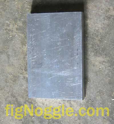
Making the pieces for this came from a single piece of 6061-T6 aluminum bar stock 3/8” thick and 2” wide. The total materials cost was less than $5.
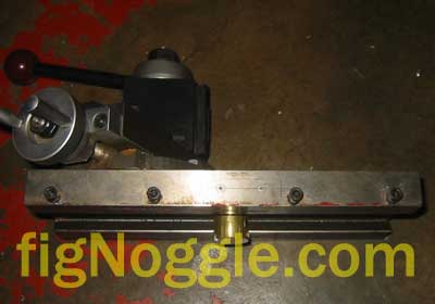
From this, we first milled the front end bracket:
This piece holds one end of the scale to the carriage.
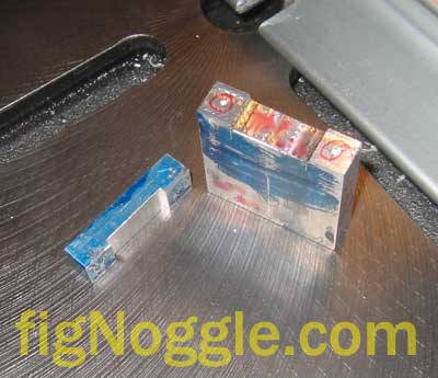
Next, we milled the scale readout bracket and spacer block. We used the ER-32 collet chuck in the Dayton/Grainger mill-drill (RF-31 clone) and ran into a clearance problem with the collet and drawbar. Luckily, the drawbar is of a soft steel that ended up being threaded into the ER collet to fit. We had to revert back to using a 7/16”-20 die to rethread the drawbar to work again with the R8 collets without resistance.
We recessed the slots so that the screws that mount the scale reading unit are flush with the bracket.
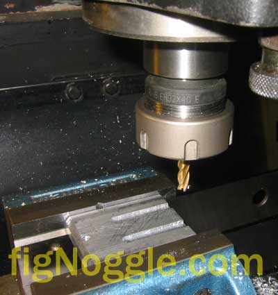
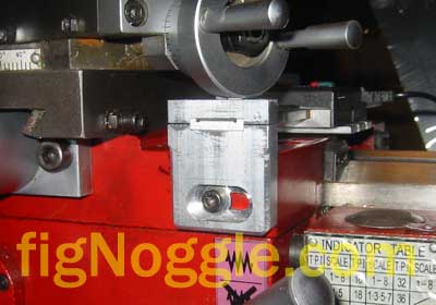
Next, we had to locate the mounting holes for the carriage and cross slide. First, we located the carriage mounting hole:
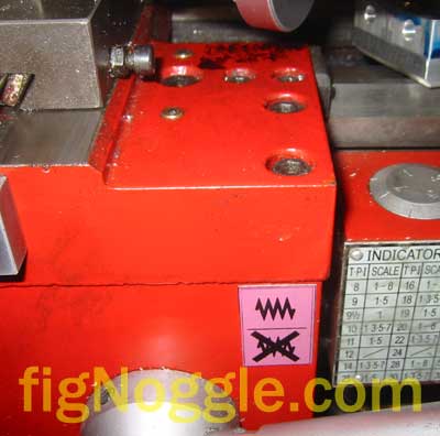
Then, once the scale was mocked up to location, we identified the holes on the cross slide, removed it, and prepped it for center drilling, drilling, and tapping:
Here’s where having a larger sized mill makes all the difference. With a 9.5“x32” table, we just removed the entire cross slide and held it in the Palmgren vise (no Kurt yet..).
Once the two holes were prepped, we put it back on the 8×12 and began mounting the scale. It was an iterative procedure. We first mounted the end bracket to the carriage:
Then we mounted the bracket to the underside of the scale readout unit and placed that next to the cross slide for general positioning.
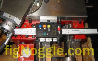
We then had to tap things around until they were level and not-binding. Once we had a generally decent idea of positioning, we loosened the brackets, retightened, then secured the bracket to the underside of the scale housing by reaching under the lathe with a screwdriver and tightening the screws. After all of this work, we end up with a nicely working X-axis DRO scale (note also the temporary Z-axis):
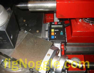
Here’s a close-up of the clearance issue of the tailstock and carriage caused by the placement of the DRO scale:
In the end, having DROs in both axes for lathe turning makes all the difference in speed. Now you can quickly get close to dimension and edge up into spec. Having DRO in general is such a time-saver. As an example, it took under a few minutes to bore out a bearing recess. Before the DRO it would take at least twice as long (perhaps longer).
Stay tuned for updates…
‘,’Finally! We mocked up and made a working prototype of the 8×12/14 cross slide (X-Axis) DRO scale mounting brackets.
‘,’
Finally! We mocked up and made a working prototype of the 8×12/14 cross slide (X-Axis) DRO scale mounting brackets.
‘,”,’8x128x14-Small-Lathe’,”,1,’Comment’,0,4,1,1,’article’,”,”,’8×1214-lathe-x-axis-cross-slide-dro-mounted’,”,”,”,”,”,”,”,”,”,”,’0edebc24c181799ebd1e657dd0416144′,’2007-01-29′);
