(277,’2007-03-10 23:03:49′,’david’,’2007-03-10 23:09:23′,’david’,’Installing The 8×12 Lathe Backsplash / Splash Guard’,”,’When ordering accessories such as the backsplash / splash guard for the 8×12 mini-lathe from Harbor Freight, you’ll need to be specific since there’s no SKU for that item.
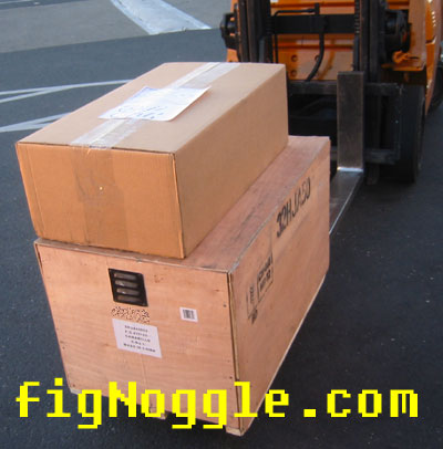
Once you receive it along with your new lathe, you may notice that the lathe has neither any tapped holes for the splash guard nor does the splash guard have suitable mounting holes for the headstock end of it. But let’s first re-enact the joy and excitement of seeing your two new boxes brought to your car via forklift at your local freight distribution center (old picture):
This splash guard sat around unmounted until recently. It was just time to either throw it away or mount it. Mounting it would require drilling and tapping three holes on the lathe and drill two new holes in the splash guard.
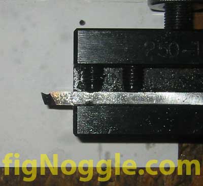
The tailstock end is easy. Just line up the end of the guard somewhat flush to the end of the bed and mark it. We used 1/4″x20TPI here:

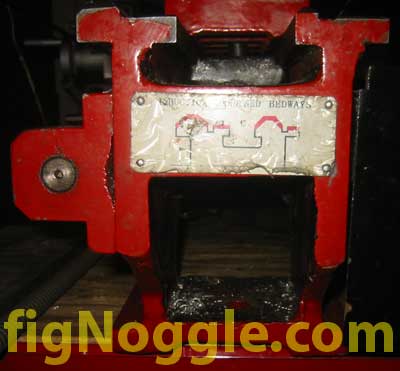
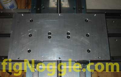
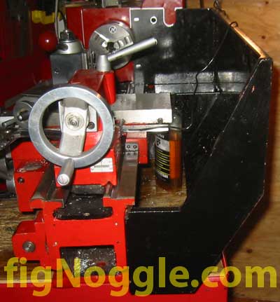
Next came the somewhat time-consuming part. We had to make sure the guard was closely parallel to the lathe bed so with the back cover of the electric switch box removed, we used some vise grips to hold the guard to the box sheet metal. After rough positioning and marking its location (as noted by the silver colored Sharpie permanent marker), we drilled two 5/16″ dia. holes roughly 2″ apart from each other about 2″ from the front edge of the splash guard.

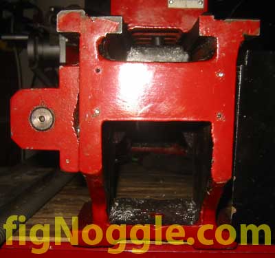
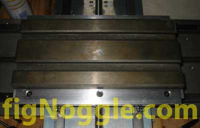
Then, we repositioned the splash guard back on and located the two holes again. Finally we drilled and tapped the two corresponding 1/4″x28 TPI holes. We’re using finder pitched threads since we’re threading into sheet metal this time.
Note that the existing two slotted holes were not used since they protrude into the cast iron head of the headstock. We just kept it simple and used the sheet metal box that houses the electrical wiring.
After 15 minutes or so, the splash guard was finally mounted!
 ‘,’
‘,’
When ordering accessories such as the backsplash / splash guard for the 8×12 mini-lathe from Harbor Freight, you’ll need to be specific since there’s no SKU for that item.
Once you receive it along with your new lathe, you may notice that the lathe has neither any tapped holes for the splash guard nor does the splash guard have suitable mounting holes for the headstock end of it. But let’s first re-enact the joy and excitement of seeing your two new boxes brought to your car via forklift at your local freight distribution center (old picture):
This splash guard sat around unmounted until recently. It was just time to either throw it away or mount it. Mounting it would require drilling and tapping three holes on the lathe and drill two new holes in the splash guard.
The tailstock end is easy. Just line up the end of the guard somewhat flush to the end of the bed and mark it. We used 1/4“x20TPI here:
Next came the somewhat time-consuming part. We had to make sure the guard was closely parallel to the lathe bed so with the back cover of the electric switch box removed, we used some vise grips to hold the guard to the box sheet metal. After rough positioning and marking its location (as noted by the silver colored Sharpie permanent marker), we drilled two 5/16” dia. holes roughly 2” apart from each other about 2” from the front edge of the splash guard.
Then, we repositioned the splash guard back on and located the two holes again. Finally we drilled and tapped the two corresponding 1/4“x28 TPI holes. We’re using finder pitched threads since we’re threading into sheet metal this time.
Note that the existing two slotted holes were not used since they protrude into the cast iron head of the headstock. We just kept it simple and used the sheet metal box that houses the electrical wiring.
After 15 minutes or so, the splash guard was finally mounted!
‘,’When ordering accessories such as the backsplash / splash guard for the 8×12 mini-lathe from Harbor Freight, you’ll need to be specific since there’s no SKU for that item.
Once you receive it along with your new lathe, you may notice that the lathe has neither any tapped holes for the splash guard nor does the splash guard have suitable mounting holes for the headstock end of it. But let’s enjoy the excitement of seeing your two new boxes brought to your car via forklift at your local freight distribution center (old picture):
‘,’
When ordering accessories such as the backsplash / splash guard for the 8×12 mini-lathe from Harbor Freight, you’ll need to be specific since there’s no SKU for that item.
Once you receive it along with your new lathe, you may notice that the lathe has neither any tapped holes for the splash guard nor does the splash guard have suitable mounting holes for the headstock end of it. But let’s enjoy the excitement of seeing your two new boxes brought to your car via forklift at your local freight distribution center (old picture):
‘,”,’8x128x14-Small-Lathe’,”,1,’Comment’,0,4,1,1,’article’,”,”,’installing-the-8×12-lathe-backsplash’,”,”,”,”,”,”,”,”,”,”,’9cb495a41f5bb4e63069c36ddb4d3f68′,’2007-03-10′);