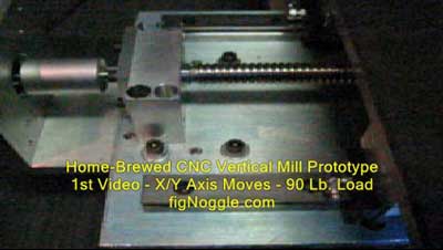
(244,’2006-09-07 12:00:00′,’figNoggle’,’2007-03-13 07:44:34′,’david’,’Home-Brewed CNC Vertical Milling Machine – Introduction’,”,’For many months we’ve been thinking about building a home-brewed CNC mill that was bench-sized, relatively easy to fabricate and assemble (with a pretty good degree of accuracy, say +/- 0.001 – type work), costs somewhere around $000 and has a greater work envelope than the X2 and even the X3 mills from Sieg.
We’ll most likely use the motor/spindle assembly from Sieg’s X2 mini-mill or X3 small-mill, linear slides from THK (or others), and readily available materials such as 6061-T6 aluminum and cold-rolled steel plates, and metal tubing. Well, that’s the general idea. If you have ever read the 5bears website, you’ll see that a home-brewed CNC machine can be made. Unfortunately we never get to see the last few pages of his work, but the first 10 or so gives a general idea of how he accomplished the building of his machine.
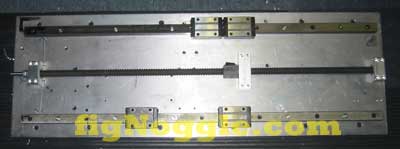
We began by using some stock we had in-house. It also helped that we have some pretty nice quality NSK linear bearings of the 20mm variety spec’d for high-load and are preloaded and matched between bearings and rails.
After the rails were layed out using nothing more than a hand drill and calipers, over the course of the 30″ of rail, there’s a deviation of roughly 0.003″. It’ll work. According to NSK, their permissible deviation is much less, but in order to achieve this, we would need to make a jig for identical spacing or spend longer positioning it using other means.
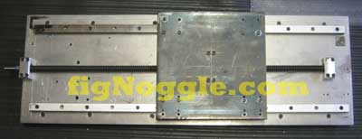
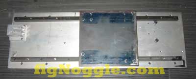
The 3/8″ aluminum plate could have been 1/2″ for stiffness, but the underside has two 1.5″ square metal tubing to help brace it some. We can easily stand a hefty person on it and have it slide easily back and forth. But that’s only after mounting the 10″ square 1/2″ cold rolled steel plate on the four bearings:
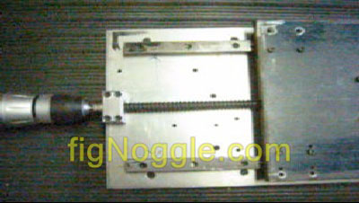
You’ll see why measuring twice (or more) and cutting once makes a lot of sense! We used a drill press to make the holes since the X2 mill was too small for this job. BTW, that’s another requirement: to be able to make this using just the “small” machines in the common home garage/workshop.
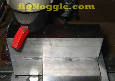
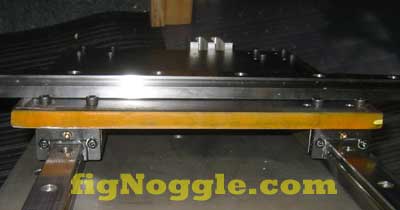
Initially after tightening the steel saddle plate to the bearings, it became more difficult to move along the rails. The reason is simple: the plate’s not straight! (Guess you could have figured that one out 
As you can kind of see, by placing another rail (which is ground flat and true) on top of the steel plate you can see the concave “dip” in the middle. The “trick” here is to secure in a diagonal pattern the bolts to the bearings and to make sure not to overtighten them. The real solution is to have a machined flat plate or use an aluminum extruded plate since it’ll be flatter and truer than the cheap steel.
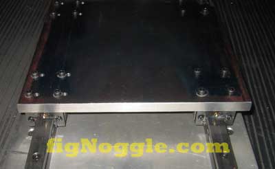
After a few hours (most of it was spent aligning things), we end up with this:
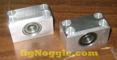
The reason you see the block and bolts at the ends of the plate are to prevent the saddle from rolling off the rails when the assembly is put into an upright position (this also needs to be able to be shipped in pieces :).
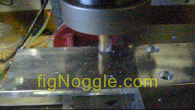
If you’ve read our X2 Mini-Mill how-tos, you’ll have already seen an inexpensive rolled ball screw and ball nut being used. We’ll do the same here since we’re reserving the ground ones for other projects. Here’s a picture of a simple 1″ square aluminum made into a flange. Perfect fit! We used the X2 CNC for milling the 0.870″ diameter hole for the ball nut thread.
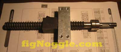
That’s it for now. In the next installment, we’ll make end blocks and mount the screw (with NEMA 23 and 34 motor mounts) onto the X-axis and take it for a test run..’
‘,’
For many months we’ve been thinking about building a home-brewed CNC mill that was bench-sized, relatively easy to fabricate and assemble (with a pretty good degree of accuracy, say +/- 0.001 – type work), costs somewhere around $000 and has a greater work envelope than the X2 and even the X3 mills from Sieg.
We’ll most likely use the motor/spindle assembly from Sieg’s X2 mini-mill or X3 small-mill, linear slides from THK (or others), and readily available materials such as 6061-T6 aluminum and cold-rolled steel plates, and metal tubing. Well, that’s the general idea. If you have ever read the 5bears website, you’ll see that a home-brewed CNC machine can be made. Unfortunately we never get to see the last few pages of his work, but the first 10 or so gives a general idea of how he accomplished the building of his machine.
We began by using some stock we had in-house. It also helped that we have some pretty nice quality NSK linear bearings of the 20mm variety spec’d for high-load and are preloaded and matched between bearings and rails.
After the rails were layed out using nothing more than a hand drill and calipers, over the course of the 30” of rail, there’s a deviation of roughly 0.003”. It’ll work. According to NSK, their permissible deviation is much less, but in order to achieve this, we would need to make a jig for identical spacing or spend longer positioning it using other means.
The 3/8” aluminum plate could have been 1/2” for stiffness, but the underside has two 1.5” square metal tubing to help brace it some. We can easily stand a hefty person on it and have it slide easily back and forth. But that’s only after mounting the 10” square 1/2” cold rolled steel plate on the four bearings:
You’ll see why measuring twice (or more) and cutting once makes a lot of sense! We used a drill press to make the holes since the X2 mill was too small for this job. BTW, that’s another requirement: to be able to make this using just the “small” machines in the common home garage/workshop.
Initially after tightening the steel saddle plate to the bearings, it became more difficult to move along the rails. The reason is simple: the plate’s not straight! (Guess you could have figured that one out
As you can kind of see, by placing another rail (which is ground flat and true) on top of the steel plate you can see the concave “dip” in the middle. The “trick” here is to secure in a diagonal pattern the bolts to the bearings and to make sure not to overtighten them. The real solution is to have a machined flat plate or use an aluminum extruded plate since it’ll be flatter and truer than the cheap steel.
After a few hours (most of it was spent aligning things), we end up with this:
The reason you see the block and bolts at the ends of the plate are to prevent the saddle from rolling off the rails when the assembly is put into an upright position (this also needs to be able to be shipped in pieces :).
If you’ve read our X2 Mini-Mill how-tos, you’ll have already seen an inexpensive rolled ball screw and ball nut being used. We’ll do the same here since we’re reserving the ground ones for other projects. Here’s a picture of a simple 1” square aluminum made into a flange. Perfect fit! We used the X2 CNC for milling the 0.870” diameter hole for the ball nut thread.
That’s it for now. In the next installment, we’ll make end blocks and mount the screw (with NEMA 23 and 34 motor mounts) onto the X-axis and take it for a test run..’
‘,’For many months we’ve been thinking about building a home-brewed CNC mill that was bench-sized, relatively easy to fabricate and assemble (with a pretty good degree of accuracy, say +/- 0.001 – type work), costs somewhere around $000 and has a greater work envelope than the X2 and even the X3 mills from Sieg.
‘,’
For many months we’ve been thinking about building a home-brewed CNC mill that was bench-sized, relatively easy to fabricate and assemble (with a pretty good degree of accuracy, say +/- 0.001 – type work), costs somewhere around $000 and has a greater work envelope than the X2 and even the X3 mills from Sieg.
‘,”,’Home-Brewed-CNC-Vertical-Mill’,”,0,”,0,4,1,1,’article’,”,”,’home-brewed-cnc-vertical-milling-machine-introduction’,”,”,”,”,”,”,”,”,”,”,’f1a7c884f9057e4e8753a43a8f3f0d18′,’2006-09-07′);