(234,’2006-08-02 12:00:00′,’figNoggle’,’2007-01-29 01:05:03′,’david’,’8×12 CNC Project – Installing DRO Scales’,”,’The order from Shars arrived the other day with some problems (more on this later). The list of goodies included more toolholders for the AXA Series 100 sized quick change tool post (QCTP), another DRO display, the scales themselves, and a demagnetizer (actually this was from ENCO).
We’ve been limited by the number of toolholders in this small shop, so having extra holders is a nice addition. This means all of the bits have a home, “quick changes” are indeed quick. In fact, more tooling is on the list.
Some people may wonder why DROs are even needed on this lathe if the lathe is to be CNC’d. Same reasoning as before: we sometimes need to quickly chuck in a workpiece and have at it. With DROs it takes the guesswork out of handcranking (how many rotations and notches is 1.452 inches?). As it turns out, after installing the Z axis DRO scale, we ran some unscientific tests of notch counting versus DRO reading. The results were pretty close (we were surprised by the result)! In many iterations, counting notches on the crank yielded positioning within 0.005″!
So, first things first – let’s take a look at the new toys!
Some new holders. Interesting note is that the Phase2 version is basically identical to the Shars brand (which actually isn’t branded at all):

Here’s a close-up of the two. The Phase 2 has a laser-etched name. Both are “250-101″ model numbers.

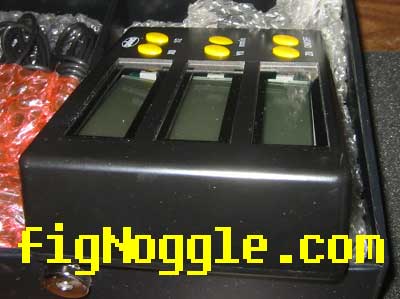
Now, the DRO readout is a LCD version that actually displays to the ten thousandths (but who can really work with those accuracies on these machines?). The main differences between this one and the one purchased from Lathemaster (Positron 3A) are the following:
1. LED vs LCD
2. display readouts to the ten thousandths
3. size
4. “look and feel”
Here are the two of them next to each other:
I happen to personally like the Positron model better. The Shars unit has a nicely backlit green LCD display, but overall build quality is low.
That was the X axis display that was loose inside the box. Looks like they didn’t use any thread locking compound:

That picture actually was taken after I had put the loose nut back onto the bolt that held one side of the display:
By the way, the box was all scratched up like it had been used. The cables looked like they had been re-wound after being undone and the power supply was all scuffed up. My guess is that it’s a return item that was passed on to us! For shame! I’ve emailed Shars about this and we’ll see how they handle this one (more on this later).
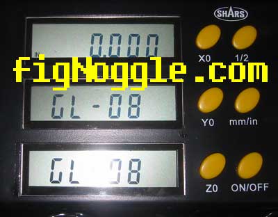
One more note about the display.. It seems to have erratic power-on status indicators. According to the manual, the “GL-08″ means to check the connections which happen to be RJ-12 (phone jack connectors!):
Here’s a video of what I’m talking about.
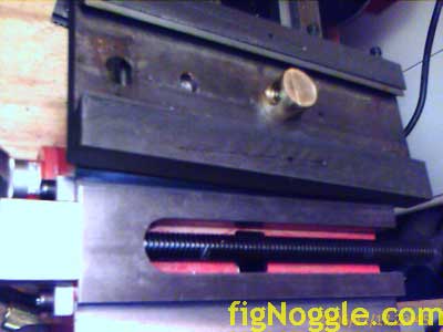
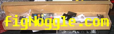
On to the scales! For the 8×1 the Z axis will use a 18″ horizontal scale while the X will use a 6″ vertical. Orientation ultimately won’t matter much since the display will be used. But, just in case the box fails, it’s nice to still be able to resort back to the scale units:
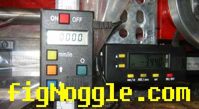
What’s interesting about this picture is that the horizontal unit (shown mounted to the lathe) has another feature that prevents it from being reset to 0 from the display unit. This was quite confusing since the Positron model and its displays didn’t offer this function. Also of interest is that a picture was posted on the website last year showing the scale on the X2 mini-mill with “INC” on the scale display. This is the same function that prevented the Shars display from zero-ing the scale. Hmm.
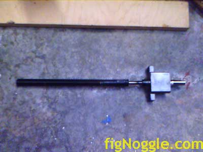
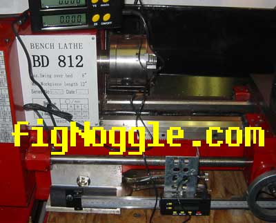
After a quick mock-up of the Z-axis scale positioning, it was mounted to the lathe using scrap pieces of material. This is just for testing purposes. TIP! If we use KISS (keep it simple, stupid), a plain plastic bag mounted over the scale display and ruler protects it from swarf. Not the most elegant or pretty solution, but it works and is cheap! We’re going to look into this as a solution to protect exposed scales.
Here’s the scale mounted to the lathe:
It was missing the “Z-bracket” that’ shown provided with the 6″ vertical unit:
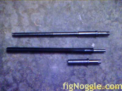
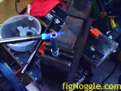
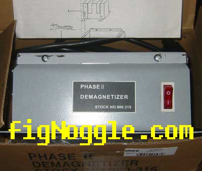
One of the things that occurs when turning steels is that they somehow get magnetized. Many of the leadscrews turned on the 8×1 for example, end up being magnetize. So, to undo this, we bought a Phase2 demagnetizer (from ENCO):
Works like a charm!
That’s it for this batch of goodies. We’ll be posting a write-up on the two models of DRO displays. At least for now you can see them both side-by-side.
And, as the scales become more permanently fixed to the lathe, we’ll show that as well.
Here’s a “shocking” Part 2 of the DRO installation…‘
‘,’
The order from Shars arrived the other day with some problems (more on this later). The list of goodies included more toolholders for the AXA Series 100 sized quick change tool post (QCTP), another DRO display, the scales themselves, and a demagnetizer (actually this was from ENCO).
We’ve been limited by the number of toolholders in this small shop, so having extra holders is a nice addition. This means all of the bits have a home, “quick changes” are indeed quick. In fact, more tooling is on the list.
Some people may wonder why DROs are even needed on this lathe if the lathe is to be CNC’d. Same reasoning as before: we sometimes need to quickly chuck in a workpiece and have at it. With DROs it takes the guesswork out of handcranking (how many rotations and notches is 1.452 inches?). As it turns out, after installing the Z axis DRO scale, we ran some unscientific tests of notch counting versus DRO reading. The results were pretty close (we were surprised by the result)! In many iterations, counting notches on the crank yielded positioning within 0.005”!
So, first things first – let’s take a look at the new toys!
Some new holders. Interesting note is that the Phase2 version is basically identical to the Shars brand (which actually isn’t branded at all):
Here’s a close-up of the two. The Phase 2 has a laser-etched name. Both are “250-101” model numbers.
Now, the DRO readout is a LCD version that actually displays to the ten thousandths (but who can really work with those accuracies on these machines?). The main differences between this one and the one purchased from Lathemaster (Positron 3A) are the following:
1. LED vs LCD
2. display readouts to the ten thousandths
3. size
4. “look and feel”
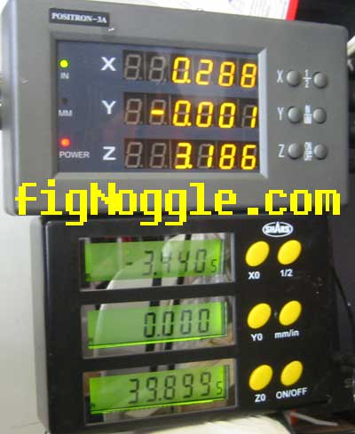
Here are the two of them next to each other:
I happen to personally like the Positron model better. The Shars unit has a nicely backlit green LCD display, but overall build quality is low.
That was the X axis display that was loose inside the box. Looks like they didn’t use any thread locking compound:
That picture actually was taken after I had put the loose nut back onto the bolt that held one side of the display:
By the way, the box was all scratched up like it had been used. The cables looked like they had been re-wound after being undone and the power supply was all scuffed up. My guess is that it’s a return item that was passed on to us! For shame! I’ve emailed Shars about this and we’ll see how they handle this one (more on this later).
One more note about the display.. It seems to have erratic power-on status indicators. According to the manual, the “GL-08” means to check the connections which happen to be RJ-12 (phone jack connectors!):
Here’s a video of what I’m talking about.
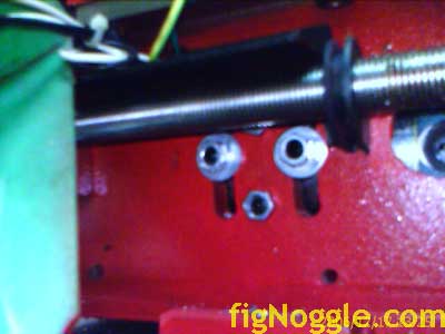
On to the scales! For the 8×1 the Z axis will use a 18” horizontal scale while the X will use a 6” vertical. Orientation ultimately won’t matter much since the display will be used. But, just in case the box fails, it’s nice to still be able to resort back to the scale units:
What’s interesting about this picture is that the horizontal unit (shown mounted to the lathe) has another feature that prevents it from being reset to 0 from the display unit. This was quite confusing since the Positron model and its displays didn’t offer this function. Also of interest is that a picture was posted on the website last year showing the scale on the X2 mini-mill with “INC” on the scale display. This is the same function that prevented the Shars display from zero-ing the scale. Hmm.
After a quick mock-up of the Z-axis scale positioning, it was mounted to the lathe using scrap pieces of material. This is just for testing purposes. TIP! If we use KISS (keep it simple, stupid), a plain plastic bag mounted over the scale display and ruler protects it from swarf. Not the most elegant or pretty solution, but it works and is cheap! We’re going to look into this as a solution to protect exposed scales.
Here’s the scale mounted to the lathe:
It was missing the “Z-bracket” that’ shown provided with the 6” vertical unit:
One of the things that occurs when turning steels is that they somehow get magnetized. Many of the leadscrews turned on the 8×1 for example, end up being magnetize. So, to undo this, we bought a Phase2 demagnetizer (from ENCO):
Works like a charm!
That’s it for this batch of goodies. We’ll be posting a write-up on the two models of DRO displays. At least for now you can see them both side-by-side.
And, as the scales become more permanently fixed to the lathe, we’ll show that as well.
Here’s a “shocking” Part 2 of the DRO installation…‘
‘,”,”,”,’8x128x14-Small-Lathe’,”,0,”,0,4,1,1,’article’,”,”,’8×12-cnc-project-installing-dro-scales’,”,”,”,”,”,”,”,”,”,”,’7e3e744d0b67c70ad165008abbfe90fe’,’2006-08-02′);