(279,’2007-03-20 15:16:20′,’david’,’2007-03-20 15:16:20′,’david’,’Making A Fixture Plate For Flexible And Repeatable Workpiece And Vise Holding’,”,’We\’ve been wanting to make a fixture plate for a long time now. For those acquainted with the smallish work envelope of the X2 mini-mill, you may have had the need to reposition the vise and/or workpiece to be able to machine it properly. Truing the vise and/or workpiece is quite time consuming and can be very frustrating since every time you reposition, your origin needs to be relocated.
The beauty of a fixture plate is that it allows for flexible positioning and makes for easy repeatability to the thou or better (if care is taken in its positioning methodology and provided that the plate is made to high accuracy).
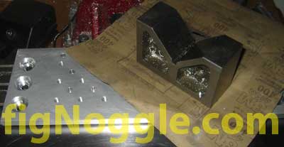
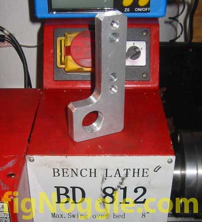
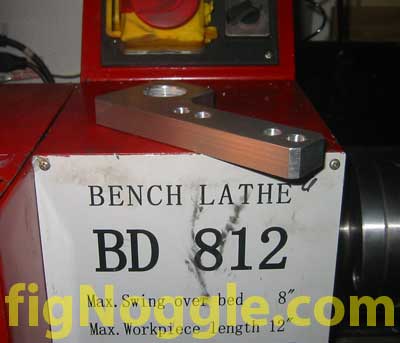
In the midst of making the mounting plates for the 8×12/14 CNC conversion of the mini-lathe, we found ourselves using the original fixture block we made for fun. It was, however, lacking in support size and the breadth of mounting holes and since we knew the mounting plates would clearly exceed the work envelope of the mini-mill, we would need a way to quickly reposition with repeatable accuracy.
Off we went to design and make a new fixture plate using the mini-mill itself.
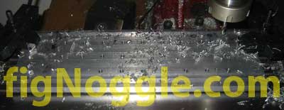
We started with a scrap of 4″ wide 3/8″ thick 6061-T6 aluminum plate. We had some of of the cast (not extruded) aluminum finished plate of 1/2″ thick (which is ideal) but were planning on using that piece for the home-brewed mini-mill project instead.
The whole concept of the fixture plate is to be able to accurately position it and secure it to the table itself and for the the plate to have threaded holes spaced accurately and equally apart from each other so that positioning doesn\’t require the use of a calculator. Finally, the plate should have a fast way to get indexed to origin of the bolt hole pattern and should have some means of indexing to the part (this is different from securing the part to the plate).
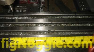
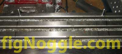
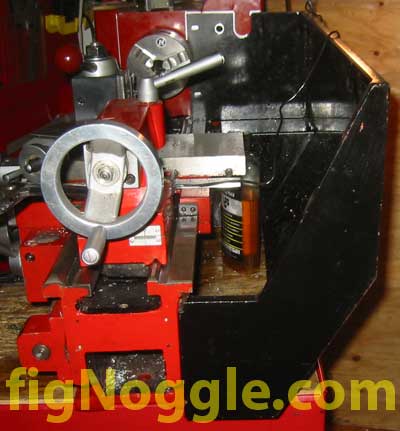
The first step was to roughly determine the length of travel we would get and provide a bit of a buffer zone. The tape measure roughly indicated that we would have a little under 8″ of X travel:
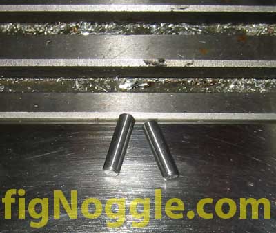
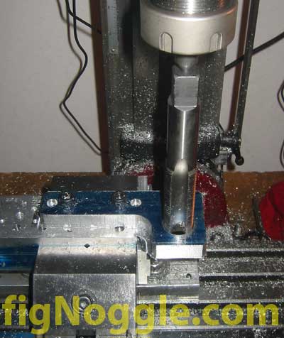
Next we need to find some ground dowel pins. We didn\’t have them on hand, but some 1/4″ would have been perfect. You can find these ground to just over 1/4″ by 0.0002″ for a tight fit. We took some drill rod type material (came from the cheap indicator base) of just under 0.250″ and chamfered the ends using the mini-lathe to get something like this:
We then marked the hole locations using with a Sharpie to space things out. We ended up with 7.500″ spacing between the two (since we\’re using the mini-mill to drill into itself – a self-operating operating), it had to be within its travel limits. Thus, the 7.500″ was dicated for us.
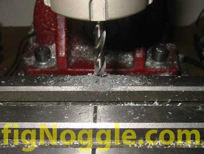
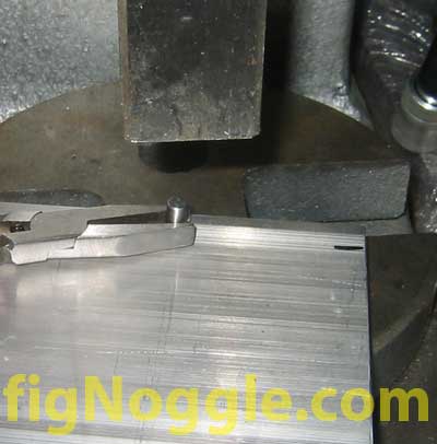
Using a drill bit slightly undersized from the dowel pin OD, we began drilling into the cast iron table:
We then tested the fit with the dowel pins inserted:
We then butted the plate (the sides weren\’t milled so the extruded edges were used – not as accurate as using a milled side that was guaranteed linear), clamped it down to the table using step clamps and drilled two corresponding through holes in the aluminum plate at the same 7.500″ interval:
Next, we inserted the pins into the plate using the arbor press. This has to be a tight fit!
Now we test fit the plate with its inserted dowel pins into the table holes – perfect, tight fit!
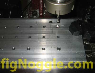
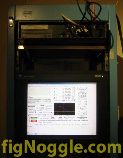
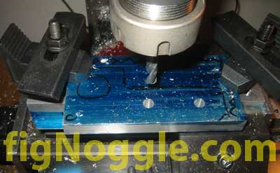
Now\’s the time for CNC drilling and reaming. We determined a origin on the plate that\’s 0.500″ x 0.500″ from the dowel pin. From this point, through holes for a 1/4″x20tpi tap (#7 drill bit) were drilled in three rows of 9 holes each spaced 1″ apart.
We then drilled an reamed 0.250″ holes also spaced 1″ apart but that are spaced 0.500″ x 0.500″ of two rows of 8 holes each in between the threaded holes. These are for dowel pins to be inserted for positioning a part when accuracy is required.
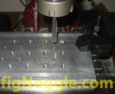
Last but not least is the origin. We simply used a 60 degree center drill so that we can insert a 60 degree pointed bit in for locating. Ideally a cut out should be used of a set dimension so that an edge finder can be used to locate it within 0.0002″ or whatever the accuracy of the edge finder is.
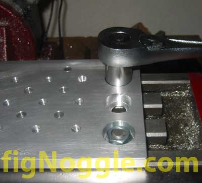
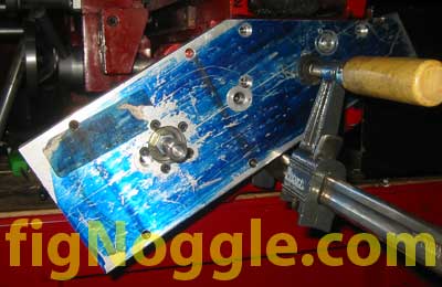
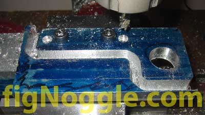
Now that the holes are completed, it\’s time to make some mounting holes so that the plate can be secured to the table using t-slot nuts. It\’s important that the nuts are just under flush from the top of the fixture plate so that there\’s no interference. This would have been much easier to accomplish with a thicker plate of at least 1/2″ thickness. With 3/8″, the threaded rod studs not only had to be very short, but only a few threads could be mated with the nut. The other alternative would be to find some thin-headed flanged bolts, but we wanted to finish this up so that we could get working on the part-making.. Here\’s a picture of the mounting setup:
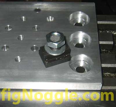
Note that the hole recesses are large. That\’s so that a socket could fit into them to tighten down the nut.
The final step was to lightly sand down the top of the plate to remove any burrs and nicks. All of the holes are chamfered, btw. We used some WD-40 and 400 grit wet/dry sandpaper to lightly make some circular passes on them. It\’s important to use something heavy and flat (not your hands/fingers) to apply equal pressure in a wide-spread contact patch:
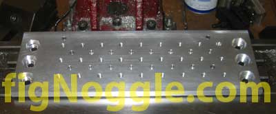
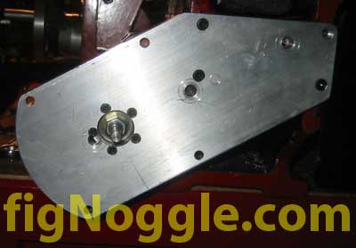
After a few hours of work (well, it might have been half a day or so), we arrived at the final plate:
Now we can begin working with vise positioning jigs for rapid positioning… As for fixturing workpieces, we\’ll show you some examples of this as we make the X-axis motor bracket for the 8×12/14 CNC mini-lathe conversion.’,’
We’ve been wanting to make a fixture plate for a long time now. For those acquainted with the smallish work envelope of the X2 mini-mill, you may have had the need to reposition the vise and/or workpiece to be able to machine it properly. Truing the vise and/or workpiece is quite time consuming and can be very frustrating since every time you reposition, your origin needs to be relocated.
The beauty of a fixture plate is that it allows for flexible positioning and makes for easy repeatability to the thou or better (if care is taken in its positioning methodology and provided that the plate is made to high accuracy).
In the midst of making the mounting plates for the 8×12/14 CNC conversion of the mini-lathe, we found ourselves using the original fixture block we made for fun. It was, however, lacking in support size and the breadth of mounting holes and since we knew the mounting plates would clearly exceed the work envelope of the mini-mill, we would need a way to quickly reposition with repeatable accuracy.
Off we went to design and make a new fixture plate using the mini-mill itself.
We started with a scrap of 4” wide 3/8” thick 6061-T6 aluminum plate. We had some of of the cast (not extruded) aluminum finished plate of 1/2” thick (which is ideal) but were planning on using that piece for the home-brewed mini-mill project instead.
The whole concept of the fixture plate is to be able to accurately position it and secure it to the table itself and for the the plate to have threaded holes spaced accurately and equally apart from each other so that positioning doesn’t require the use of a calculator. Finally, the plate should have a fast way to get indexed to origin of the bolt hole pattern and should have some means of indexing to the part (this is different from securing the part to the plate).
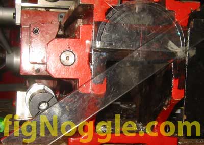
The first step was to roughly determine the length of travel we would get and provide a bit of a buffer zone. The tape measure roughly indicated that we would have a little under 8” of X travel:
Next we need to find some ground dowel pins. We didn’t have them on hand, but some 1/4” would have been perfect. You can find these ground to just over 1/4” by 0.0002” for a tight fit. We took some drill rod type material (came from the cheap indicator base) of just under 0.250” and chamfered the ends using the mini-lathe to get something like this:
We then marked the hole locations using with a Sharpie to space things out. We ended up with 7.500” spacing between the two (since we’re using the mini-mill to drill into itself – a self-operating operating), it had to be within its travel limits. Thus, the 7.500” was dicated for us.
Using a drill bit slightly undersized from the dowel pin OD, we began drilling into the cast iron table:
We then tested the fit with the dowel pins inserted:
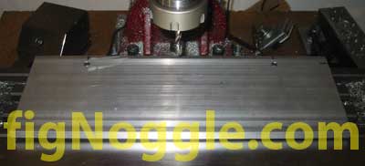
We then butted the plate (the sides weren’t milled so the extruded edges were used – not as accurate as using a milled side that was guaranteed linear), clamped it down to the table using step clamps and drilled two corresponding through holes in the aluminum plate at the same 7.500” interval:
Next, we inserted the pins into the plate using the arbor press. This has to be a tight fit!
Now we test fit the plate with its inserted dowel pins into the table holes – perfect, tight fit!
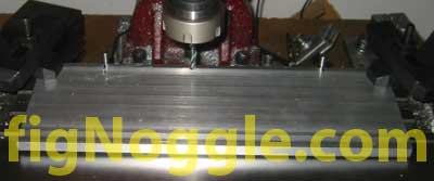
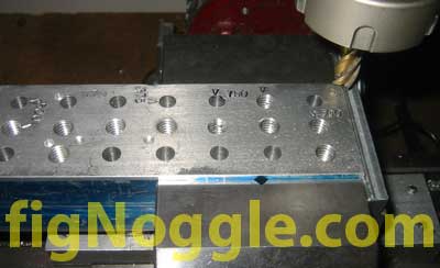
Now’s the time for CNC drilling and reaming. We determined a origin on the plate that’s 0.500” x 0.500” from the dowel pin. From this point, through holes for a 1/4“x20tpi tap (#7 drill bit) were drilled in three rows of 9 holes each spaced 1” apart.
We then drilled an reamed 0.250” holes also spaced 1” apart but that are spaced 0.500” x 0.500” of two rows of 8 holes each in between the threaded holes. These are for dowel pins to be inserted for positioning a part when accuracy is required.
Last but not least is the origin. We simply used a 60 degree center drill so that we can insert a 60 degree pointed bit in for locating. Ideally a cut out should be used of a set dimension so that an edge finder can be used to locate it within 0.0002” or whatever the accuracy of the edge finder is.
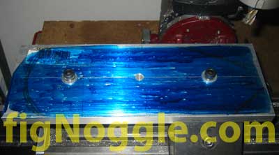
Now that the holes are completed, it’s time to make some mounting holes so that the plate can be secured to the table using t-slot nuts. It’s important that the nuts are just under flush from the top of the fixture plate so that there’s no interference. This would have been much easier to accomplish with a thicker plate of at least 1/2” thickness. With 3/8”, the threaded rod studs not only had to be very short, but only a few threads could be mated with the nut. The other alternative would be to find some thin-headed flanged bolts, but we wanted to finish this up so that we could get working on the part-making.. Here’s a picture of the mounting setup:
Note that the hole recesses are large. That’s so that a socket could fit into them to tighten down the nut.
The final step was to lightly sand down the top of the plate to remove any burrs and nicks. All of the holes are chamfered, btw. We used some WD-40 and 400 grit wet/dry sandpaper to lightly make some circular passes on them. It’s important to use something heavy and flat (not your hands/fingers) to apply equal pressure in a wide-spread contact patch:
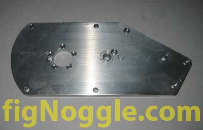
After a few hours of work (well, it might have been half a day or so), we arrived at the final plate:
Now we can begin working with vise positioning jigs for rapid positioning… As for fixturing workpieces, we’ll show you some examples of this as we make the X-axis motor bracket for the 8×12/14 CNC mini-lathe conversion.
‘,’We\’ve been wanting to make a fixture plate for a long time now. For those acquainted with the smallish work envelope of the X2 mini-mill, you may have had the need to reposition the vise and/or workpiece to be able to machine it properly. Truing the vise and/or workpiece is quite time consuming and can be very frustrating since every time you reposition, your origin needs to be relocated.
The beauty of a fixture plate is that it allows for flexible positioning and makes for easy repeatability to the thou or better (if care is taken in its positioning methodology and provided that the plate is made to high accuracy).
In the midst of making the mounting plates for the 8×12/14 CNC conversion of the mini-lathe, we found ourselves using the original fixture block we made for fun. It was, however, lacking in support size and the breadth of mounting holes and since we knew the mounting plates would clearly exceed the work envelope of the mini-mill, we would need a way to quickly reposition with repeatable accuracy.
Off we went to design and make a new fixture plate using the mini-mill itself.
‘,’
We’ve been wanting to make a fixture plate for a long time now. For those acquainted with the smallish work envelope of the X2 mini-mill, you may have had the need to reposition the vise and/or workpiece to be able to machine it properly. Truing the vise and/or workpiece is quite time consuming and can be very frustrating since every time you reposition, your origin needs to be relocated.
The beauty of a fixture plate is that it allows for flexible positioning and makes for easy repeatability to the thou or better (if care is taken in its positioning methodology and provided that the plate is made to high accuracy).
In the midst of making the mounting plates for the 8×12/14 CNC conversion of the mini-lathe, we found ourselves using the original fixture block we made for fun. It was, however, lacking in support size and the breadth of mounting holes and since we knew the mounting plates would clearly exceed the work envelope of the mini-mill, we would need a way to quickly reposition with repeatable accuracy.
Off we went to design and make a new fixture plate using the mini-mill itself.
‘,”,’Sieg-X2-Mini-Mill’,’Tooling’,1,’Comment’,0,4,1,1,’article’,”,”,’making-a-fixture-plate-for-flexible-and-repeatable-workpiece-and-vise-holding’,”,”,”,”,”,”,”,”,”,”,’9fdabdacee09443564097c43d65c8d48′,’2007-03-20′);
 (Contouring)
 (Threading by hand)
 (Completed)
 (Look at the excellent finish!)


 ‘,’
‘,’