(276,’2007-03-10 22:40:51′,’david’,’2007-03-10 22:40:51′,”,’CNC 8×12 Lathe Z-Axis Prototype’,”,’Finally, we’ve resumed posting some pictures of progress we’re making on the CNC 8×12 mini-lathe.
We had mocked up some placements of the cross-feed ballscrew a while back. Today, we’ll work on the Z-axis. First things first, we’ll get started on the 5/8″ x 5 TPI ballscrew. All that’s needed is to turn down the rough lengthed bearing journal, thread, and shaft coupling length.
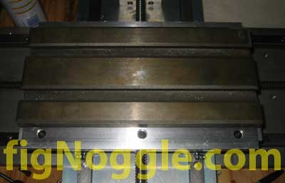
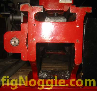
The basic concept is to mount a plate on the back end of the bed where the “Induction Hardened Bedways” label is attached.
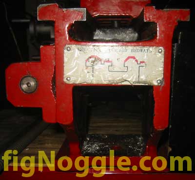
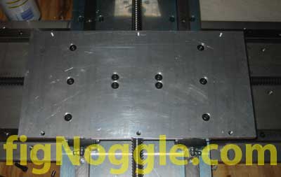
After drilling out the four rivets that hold the plate to the bed end, we end up with, well, the end of the bed with the plate removed:
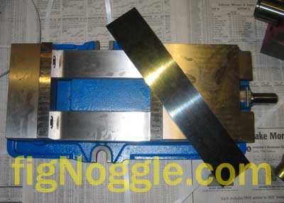
If you’ve seen us mocking up prototypes before, you’ll remember that we find the use of index cards, hot-glued cardboard, wood, and other easily-cut materials ideal for quick mock-ups.
After we roughly determined the length of the ballscrew, motor mounting plate (for both NEMA 23 and 34 framed motors), we began turning the ballscrew.
Here we’ll digress for a few moments and discuss how we’ve slowly converted to grinding our own HSS (high speed steel) tool bits instead of using carbide inserts. One of the immediate differences you’ll notice when using HSS over inserts is not only the cost savings, but that it really only takes less than a minute to create a suitable cutting tool for turning. For us, as we turn lots of ballscrews and ACME leadscrews, we’ve never found the inserts and these benchtop lathes to be ideal mates. Turning hardened alloys and even free-machining steels has always posed challenges when trying to produce a smooth finish that can be accomplished with just a few passes of fine grit sandpaper after a HSS bit-cut. We can even make a nice cutting tool for peeling away .050″ DOC of aluminum that still leaves quite a nice finish!
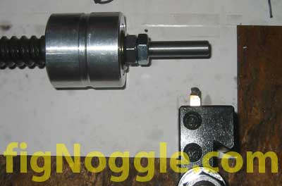
We’ll skip the usual clips of turning ballscrews turning at a lowly 240 RPM (it produced nice chips with no change in color – not even straw) and show you the final result of the shaft end with the 5/16″ bit used:
We didn’t use a post-process like wet sanding and the finish is smooth. We could polish it from here, but it’s not necessary. Here’s the front relief:
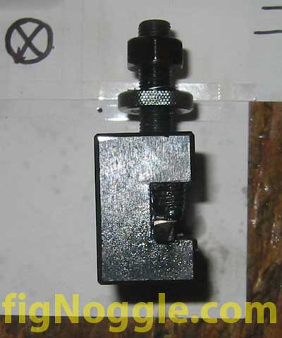
And the side relief:
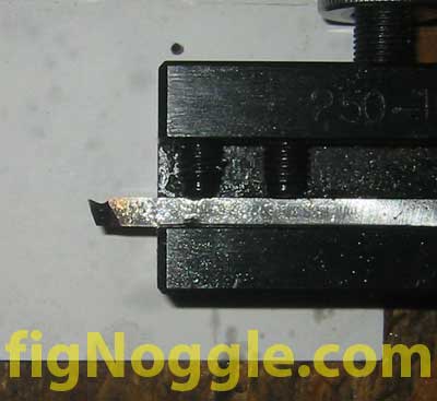
As you can see, all you need are the top, side, and front reliefs at roughly 5 degrees or so, making sure that you take into account the direction of cut (tailstock to headstock or vice versa). You can spend less than a minute (we did) and end up with a bit that doesn’t look all that great but performs beautifully.
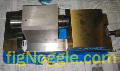
Back to the CNC conversion. We’re going to keep manual function of the lathe, so the CNC will be something you can switch over to for repetitive processes (like turning down leadscrew bearing journals).
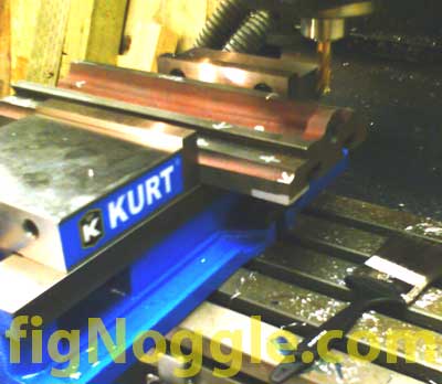
The basic procedure will be to mount the ballnut to the underside of the carriage apron and have the bearing block and shaft to the tail end of the bed:
Finally, we’ve resumed posting some pictures of progress we’re making on the CNC 8×12 mini-lathe.
We had mocked up some placements of the cross-feed ballscrew a while back. Today, we’ll work on the Z-axis. First things first, we’ll get started on the 5/8″ x 5 TPI ballscrew. All that’s needed is to turn down the rough lengthed bearing journal, thread, and shaft coupling length.
The basic concept is to mount a plate on the back end of the bed where the “Induction Hardened Bedways” label is attached.

Stay tuned…’,’
Finally, we’ve resumed posting some pictures of progress we’re making on the CNC 8×12 mini-lathe.
We had mocked up some placements of the cross-feed ballscrew a while back. Today, we’ll work on the Z-axis. First things first, we’ll get started on the 5/8” x 5 TPI ballscrew. All that’s needed is to turn down the rough lengthed bearing journal, thread, and shaft coupling length.
The basic concept is to mount a plate on the back end of the bed where the “Induction Hardened Bedways” label is attached.
After drilling out the four rivets that hold the plate to the bed end, we end up with, well, the end of the bed with the plate removed:
If you’ve seen us mocking up prototypes before, you’ll remember that we find the use of index cards, hot-glued cardboard, wood, and other easily-cut materials ideal for quick mock-ups.
After we roughly determined the length of the ballscrew, motor mounting plate (for both NEMA 23 and 34 framed motors), we began turning the ballscrew.
Here we’ll digress for a few moments and discuss how we’ve slowly converted to grinding our own HSS (high speed steel) tool bits instead of using carbide inserts. One of the immediate differences you’ll notice when using HSS over inserts is not only the cost savings, but that it really only takes less than a minute to create a suitable cutting tool for turning. For us, as we turn lots of ballscrews and ACME leadscrews, we’ve never found the inserts and these benchtop lathes to be ideal mates. Turning hardened alloys and even free-machining steels has always posed challenges when trying to produce a smooth finish that can be accomplished with just a few passes of fine grit sandpaper after a HSS bit-cut. We can even make a nice cutting tool for peeling away .050” DOC of aluminum that still leaves quite a nice finish!
We’ll skip the usual clips of turning ballscrews turning at a lowly 240 RPM (it produced nice chips with no change in color – not even straw) and show you the final result of the shaft end with the 5/16” bit used:
We didn’t use a post-process like wet sanding and the finish is smooth. We could polish it from here, but it’s not necessary. Here’s the front relief:
And the side relief:
As you can see, all you need are the top, side, and front reliefs at roughly 5 degrees or so, making sure that you take into account the direction of cut (tailstock to headstock or vice versa). You can spend less than a minute (we did) and end up with a bit that doesn’t look all that great but performs beautifully.
Back to the CNC conversion. We’re going to keep manual function of the lathe, so the CNC will be something you can switch over to for repetitive processes (like turning down leadscrew bearing journals).
The basic procedure will be to mount the ballnut to the underside of the carriage apron and have the bearing block and shaft to the tail end of the bed:
Finally, we’ve resumed posting some pictures of progress we’re making on the CNC 8×12 mini-lathe.
We had mocked up some placements of the cross-feed ballscrew a while back. Today, we’ll work on the Z-axis. First things first, we’ll get started on the 5/8” x 5 TPI ballscrew. All that’s needed is to turn down the rough lengthed bearing journal, thread, and shaft coupling length.
The basic concept is to mount a plate on the back end of the bed where the “Induction Hardened Bedways” label is attached.
Stay tuned…
‘,’Finally, we’ve resumed posting some pictures of progress we’re making on the CNC 8×12 mini-lathe.
We had mocked up some placements of the cross-feed ballscrew a while back. Today, we’ll work on the Z-axis. First things first, we’ll get started on the 5/8″ x 5 TPI ballscrew. All that’s needed is to turn down the rough lengthed bearing journal, thread, and shaft coupling length.
The basic concept is to mount a plate on the back end of the bed where the “Induction Hardened Bedways” label is attached.
‘,’
Finally, we’ve resumed posting some pictures of progress we’re making on the CNC 8×12 mini-lathe.
We had mocked up some placements of the cross-feed ballscrew a while back. Today, we’ll work on the Z-axis. First things first, we’ll get started on the 5/8” x 5 TPI ballscrew. All that’s needed is to turn down the rough lengthed bearing journal, thread, and shaft coupling length.
The basic concept is to mount a plate on the back end of the bed where the “Induction Hardened Bedways” label is attached.
‘,”,’8x128x14-Small-Lathe’,”,1,’Comment’,0,4,1,1,’article’,”,”,’cnc-8×12-lathe-z-axis-prototype’,”,”,”,”,”,”,”,”,”,”,’796a21f4602b39d10de920a4f90adbc5′,’2007-03-10′);