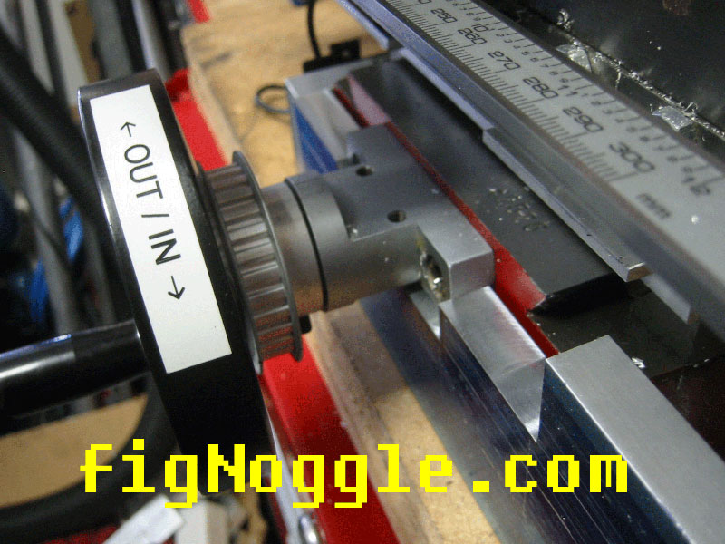
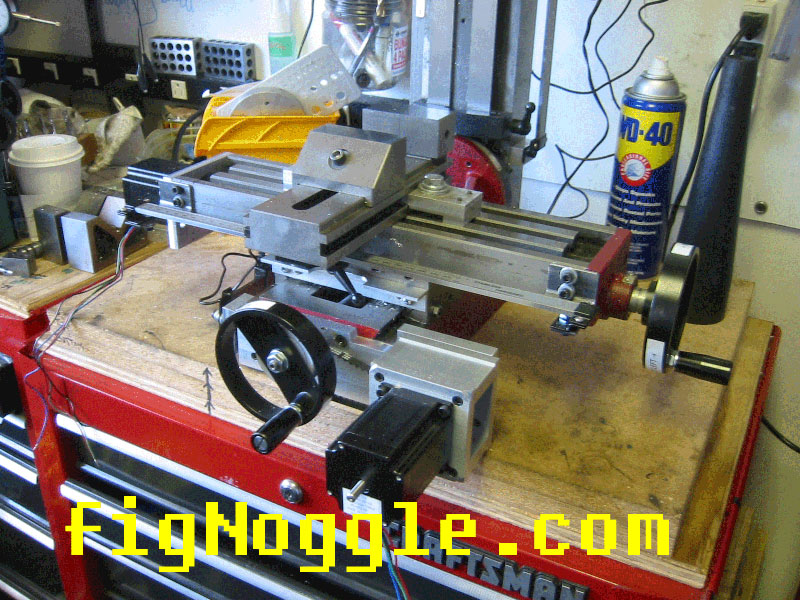
x axis coupling. i decided to mount the x axis stepper
motor on the left hand side of the bed. the acme screw had a deal for the
power feed.
update. it's difficult to get 100% parallel alignment as
i found out when running the motors at higher speed/accel. the motor would
stall and make nasty noises. so i cut down the right end of the coupling
to allow more angular clearance. i also ordered a flex coupling that
should allow up to 15 degrees. |
 |
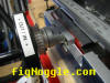
here's the pulley for the y axis getting modded for
mounting onto the handwheel. haven't seen anyone do this one yet. |
 |
note that a washer will need to be fitted to deal with the
backlash adjustment.
update. the pulley itself can be
machined down so that the washer is not needed. |
 |
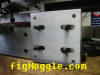
mounted. nice. |
 |
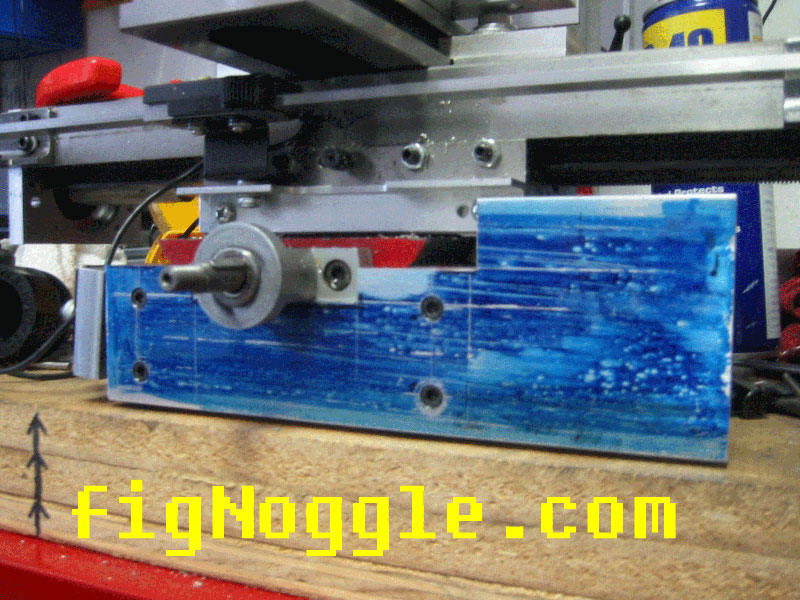
onto the to pulley contraption for the y axis. basically,
i DID NOT want the motor sticking out too far like the sterlingsteele mod.
a pulley system seemed ideal. (actually i had considered sticking the
pulley underneath the base!) |
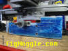 |
here's the housing of the stepper motor being made. |
 |
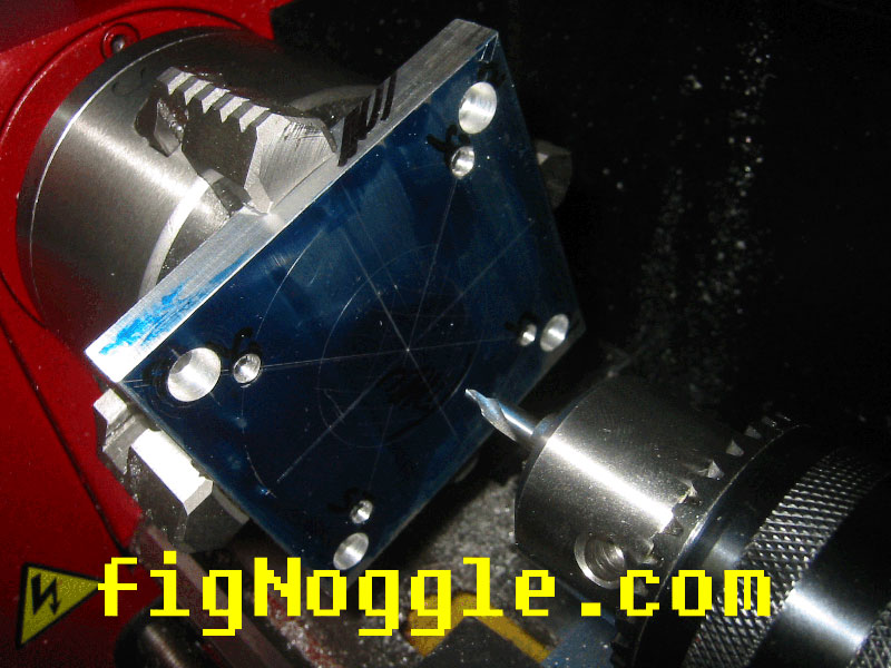
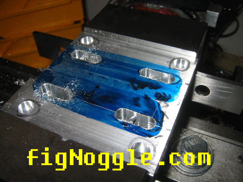
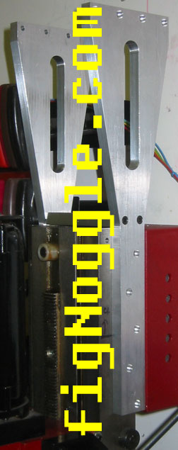
here's the plate that mounts to the baseplate. note slots
for adjustablility. |
 |
here it is cleaned up and mounted to the y axis plate. |
 |
the completed x and y axes.
update. this
is version 1 of the conversion. version 2 of the
conversion can be seen here. |
 |
here's a test of the CNC
setup
with mach and turbocnc. lots of adjusting to do. |
a brief clip of x-y. need to work on settings. 1st
attempt. with mach2. |
click for clip |
this is actually the 1st attempt. i used turbocnc with
default settings. this sounds bad. listen closely. |
click for clip |
2nd attempt. started dialing in the settings and made my
own g-code file for a small rectangle thing. mach2. not saying one is
better than the other. out of the box, mach2 is nice. |
click for clip |
here's the computer and
controller inside a rack mount 2U case. |
inside. note the wiring and xylotex controller. |
 |
here's the faceplate. not the best work (a cnc-cut one
would have been much cleaner) |
 |
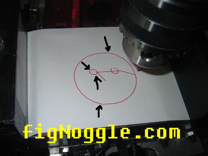
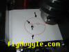
results after dialing in backlash and motor setup. |
umm, what's the deal here? is it due to the paper moving
around when the motor stops and switches directions or is it a backlash
artifact? |
 |
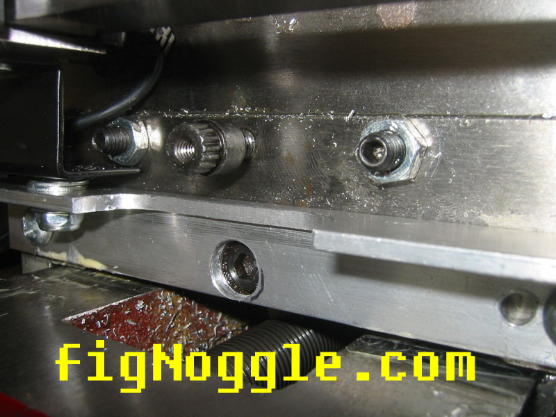
oops. it WAS the y-axis
bronze leadnut. |
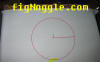
here's a 1.5" dia. circle with the backlash artifact. 0
backlash compensation in X and Y in mach2. |
 |
i had covered the adjusting bolt with the dro holder. i
drilled the hole to expose this and tightened it. |
 |
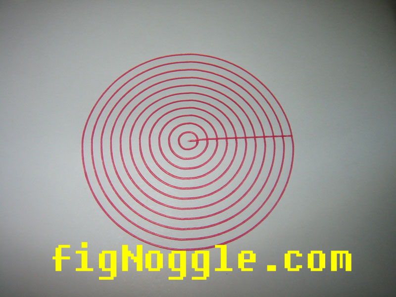
no changes in backlash compensation. here's what happened
after the nut was tightened. the same 1.5" dia. circle. much better. |
 |
ok, you can see that scale does matter. the smaller
circles show more of the backlash artifact while the larger circles show
less. |
 |
a brief clip of the concentric circles being made. |
click for clip |
next, the Z axis |
slight distraction here. roughing end mill versus 4-flute
end mill. notice the finish. also, you really can take a whole bunch of
material per cut with the roughing end mill. get some. |

 |
assembled ballscrew assembly. the ballscrew was turned in
a 7x10 mini-lathe and threaded for 3/8"x24. you'll see why later. |
 |
assembled z-axis motor assembly. this was quite a simple
way of doing it, though it didn't seem like it at first. |
 |
the side brackets are being made. tip: using index
cards for stacked parts is a great way for making sure they're gripped
tight. note that part of the design calls for a slot for aesthetics and
functionality. |
 |
the brackets are complete. note the chamfer for the
column. there was an "oops" moment when i chamfered the wrong side of the
bracket. |
 |
here are the brackets positioned. note: the column is
3.930" inches wide (in case you were wondering)
update. i've heard from other people that milling 4" in the y-axis is not
possible. it is possible. it's gets really tight at the extremes of
the milling operation but it is possible.
update. version 2 of the z-axis brackets have become
easier to machine and smaller in size.
this reminds me of something.. figured it out! |
 |
all done! here's the first pocket cut made. still need to
learn mach's coordinate system stuff. |
 |
| see the z-axis move up and down. ok, not the most exciting
clip, but there's only one other clip on the net that i've seen of the
z-axis conversion MOVING. |
click for clip |
here it's actually milling in 3D! you can see my
conversion working. |
click for clip |