HOW-TO Upgrade To ACME Leadscrews
And Acetal/Delrin Leadnuts (X-Axis)
after modifying the brass nut to a
quasi anti-backlash type, it's time to take it further. i've decided to
use a rated ACME screw (+/- 0.003"in/ft) from nook and make my own acetal/delrin
nuts. why didn't i upgrade the mini mill with ballscrews? well, since our cnc conversion retains manual function, i didn't want to make the
travel too slippery. also, to use a ballnut you'd need to hack away at the
table carriage some (in order to retain full travel) and this wasn't the preferred method.
so, the combination of acme with a
smooth acetal/delrin nut which would be able to fit in the stock cavities
is the way to go. this page has the upgrade in pictorial format.
this page is rather long so we will only talk about
the X-axis. to see the Y-axis, click here.
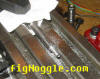
| the stuff. turns out that the X RH and the Y is LH.
this is a prototype. we'll have to re-do the X axis. |
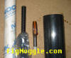
| not a super exciting picture, but here's what's
needed.
the acme screw. it's 5/8" x 8 TPI LH.
the stock screw is 5/8" x 16 TPI.
a 5/8" x 8 TPI LH tap ($$$).
a 2.5" dia. round stock of acetal/delrin.
here are its properties: matweb.com website
it appears that it's "highly" machinable, is rigid
and is an efficient material for gears and such.
|
 |
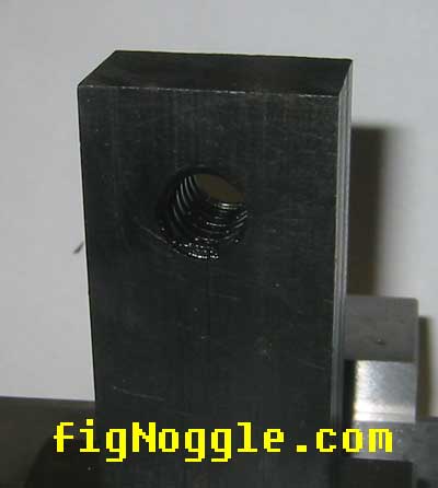
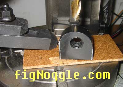
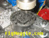
| turns out there was a piece of stock sitting around
and it looked like acetal/delrin. so i gave it a try. here it is tapped. |
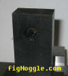 |
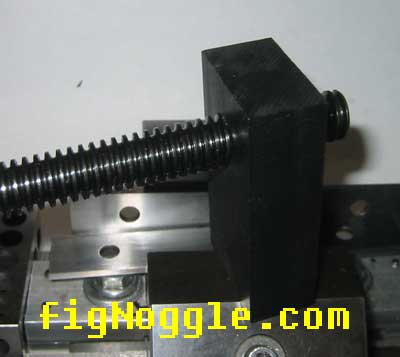
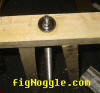
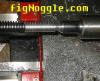
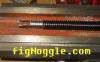
| and screwed onto the acme. 0 axial play. i think this
is a winner! it's smooth - there's a bit of friction which may be good
since the thread pitch has been cut by half. now it's time to take the entire table apart, measure
parts and start machining. unfortunately, since this is the only mill
here, i'll have to re-assembly it so i can perform some operations on
the mill prior to final assembly and testing. |
 |
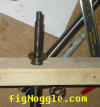
| prep work on the leadscrew |
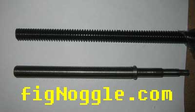
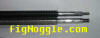
| here's the leadscrew stock and the stock Y-axis
screw.
we're showing the X-axis for now. |
 |
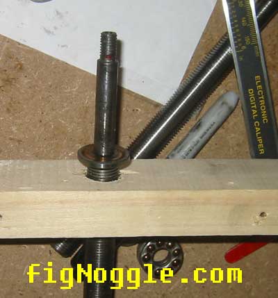
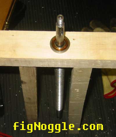
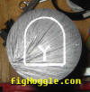
| first remove the bearings from the leadscrew.
since there's no arbor press or bearing/gear
puller, we use the good old-fashioned method - hammer it out!
this wood is from the 8x12 crate! |
 |
| we stand it up and prep for hammering. |
 |
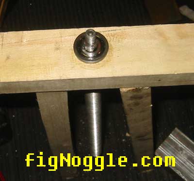
| almost out. it's a VERY tight fit. |
 |
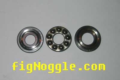
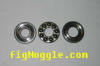
| here is one set of thrust bearings. there are two. |
 |
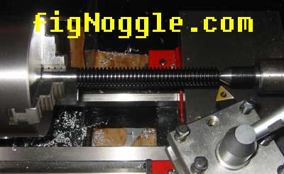
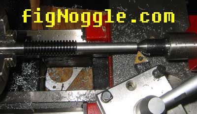
| turn and thread the leadscrew |
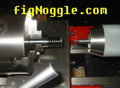
| now we chuck the leadscrew (after cutting it to
approximate length).
we use a 0.001"
shimstock to protect the threads. works better than index cards. |
 |
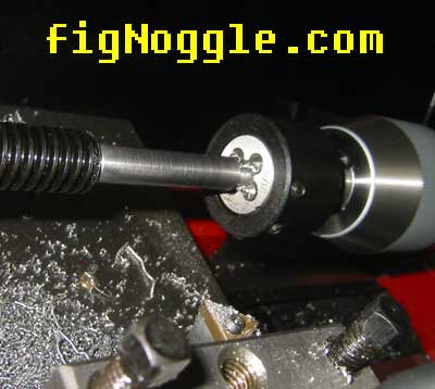
| we're prepping it for a dead center (the 8x12 doesn't
come with a live center and there's been little work on the lathe so far -
but the upcoming project is to install the PhaseII QCTP) |
 |
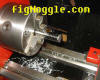
| here we go... |
 |
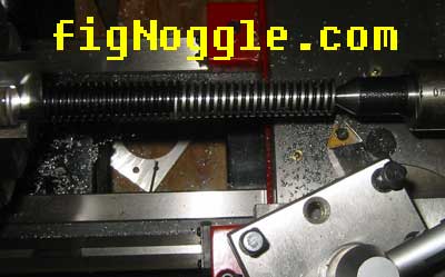
| first pass. |
 |
| second pass. |
 |
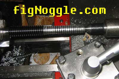
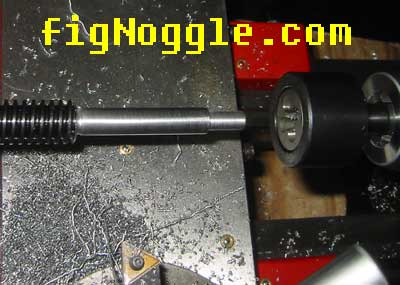
| now we're getting close to the nominal shaft diameter
sans thread. |
 |
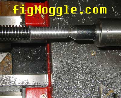
| it's turned to bearing ID dimensions. |
 |
| the threaded end is turned further. |
 |
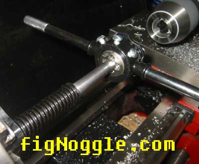
| now we start tapping. we start with a holder chucked
to a drill chuck. |
 |
| then we move onto one with a handle (there are mods
to mix the two together - that will be a project in the future) |
 |
| threaded and ready to go. |
 |
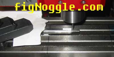
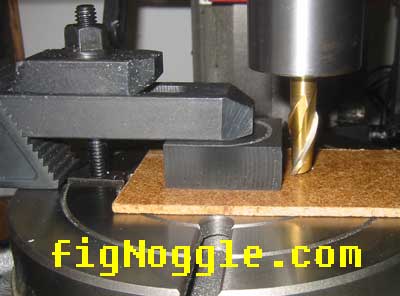
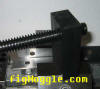
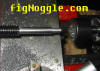
| now we have to make a key slot and tail slot. |
| here's the bit used - a 1/16" 4 flute end mill. it's
tiny!
for this operation, we had to undo the torsion spring and use the cnc function to gain the extra z
travel down towards the table. |
 |
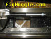
| we strapped the screw directly onto the bed. |
 |
| the slot is being cut at 0.005" per pass.
if we had the right size diameter end mill, this
operation would have been much faster. |
 |
| done. fits perfectly. |
 |
| prep work on the nut |
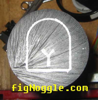
| sharpie markers now also come in metallic silver -
great for marking black items.
here's a
trace of the Y-nut. (which is not covered on this page) |
 |
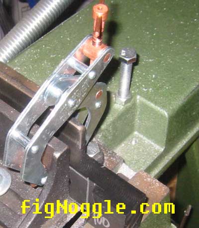
| tip. those kant-twist clamps are great for holding
small pieces to the 4x6 bandsaw. it clears everything and provides great
grip. |
 |
| now we put the nut stock on a rotary table.
this is prototype so we didn't center the stock
perfectly. |
 |
| and this is what happened. it's skewed. but it fits
the general profile of the stock nut and fits perfectly in the cavity. |
 |
| a side by side. |
 |
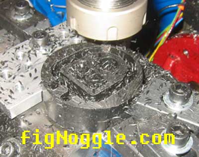
| update! here's a cnc-milled acetal nut being
machined. |
 |
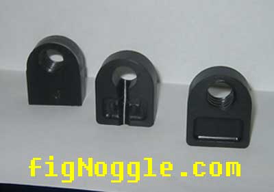
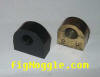
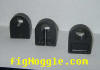
| another side by side of the acetal nut prototypes.
the far left is the same one shown above next to the brass nut.
the middle one has a semi-oops but also has something
to do with an anti-backlash mechanism.
the far right is the completed cnc acetal nut. |
 |
| test fit. now we're getting ready.. |
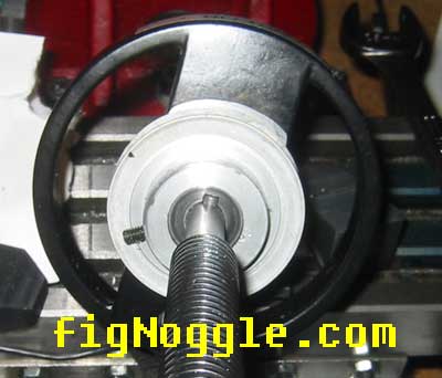
| the handle fits perfectly on the shaft. even the key
slot is right on. |
 |
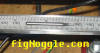
| here's side-by-side of the front end of the screw |
 |
| and here's the rear end. note that the new screw
turned to the dimensions of the stock leadscrew still leave a bit of
thread. this is ok. |
 |
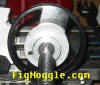
| a test fit of the thrust bearings. not too tight
(like before). it's a nice slip fit. |
 |
| assembly and testing |
| the nut goes into the cavity. |
 |
| the handle is installed and tightened just tight
enough to remove axial play but have smooth rotation. |
 |
| this is the rear of the screw. |
 |
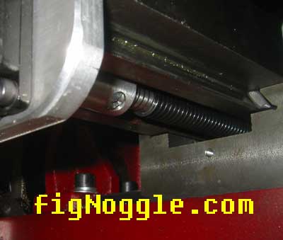
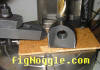
| installed on the cnc setup. |
 |
| there's 0.006" of backlash (i think) - there' still
more work to be done to the nut. it'll have it's own anti-backlash
mechanism.
it's definitely an improvement over the stock
setup. smooth action, no binding like before.
it took less than one minute setup the gibs and
nut placement. no play and the result i got is shown in the video of the
x-axis doing a 1" jog and back. goes back to zero!
using the x-axis manually is VERY nice.
now onto the y-axis.
in case you're wondering, these plans and
kits will be
available. the y-axis will have a new retaining bearing block with
bearings. should be smooth. |
click to see
video |
| click here to
see the Y-axis |